This project hasn’t reached the state of a Minimum Viable Product, but I’ve learned a lot that may be useful for others pursuing similar builds. What follows is a writeup on what started as an Associate of Engineering capstone project and evolved into a winter-break tinkering project.
I’ll walk through background research, product requirements, prototyping, troubleshooting, and proposed validation and testing methods for a portable water treatment device scoped for backpacking, camping, and developed-world urban trips.
If I were to take this project further, I would first tighten up the market definition. The distinction between a humanitarian crisis-response tool and a premium consumer bottle was not drawn clearly enough when this project began, and that ambiguity shows up in some of the early design choices.
Initial Concept
I’ve been circling around off-grid and energy projects recently, so for my Associate of Engineering capstone project I decided to explore drinking water treatment you can throw in a backpack.
The idea itself isn’t new. People have been boiling and filtering water in simple containers since long before modern hiking gear, but the current wave of compact, consumer-ready systems is relatively new. Some of the most modern developments include:
- Sawyer Squeeze
- Katadyn Hiker Pro
- Katadyn Steripen Ultra UV Water Purifier
- MSR Guardian
- LifeStraw Product Line
- Faircap Product Line
I wanted something in the sweet spot between “Press-to-filter” bottles like the Grayl GeoPress and self-disinfecting bottles like the Larq PureVis 2. The goal was to see how close we could get to a practical, repeatable design, and at what total cost. Ease of use, ease of cleaning, the option for solar charging, and being relatively easy to recreate all influenced the concept.
The user story that ended up anchoring the design was:
User Story
“As someone who travels, camps, or works in places where tap water isn’t a viable option,
I need a compact bottle that can handle turbidity, taste, and biological contamination,
So that I can safely drink without hauling single-use filter bottles, iodine tablets, boiling gear, or chlorine/bleach treatments.”
– Potential User
While addressing this problem, I wanted to see whether we could improve on existing solutions rather than just copy one. Instead of choosing either filtration or UVC, I staged them, which is how larger municipal UVC treatment processes are typically configured, but is much less common in a water-bottle form factor.
The stages we landed on were:
- A refillable filter block in a lower inner chamber to handle turbidity (Suspended solids) and reduce chlorine, lead, and other dissolved contaminants.
- A UVC LED lamp in an upper inner chamber to target microorganisms such as protozoa, bacteria, and viruses. Viruses (Adenovirus in particular) are among the more UV-resistant organisms used in drinking-water guidance, so designing for virus-level dosing is a deliberately conservative target.
Discovery
To establish the requirements and constraints for this build, I began with discovery. I benchmarked leading commercial products to understand real-world UX and published performance claims, then cross-checked those capabilities against academic UV reactor work to ground the design in dose, geometry, and validation concepts. This work resulted in a set of Product Requirements (Performance, safety, usability) that drive the prototype decisions to follow.
Commercial Designs
The products below represent the strongest benchmarks I found for filtration-first architectures and lid-integrated UVC systems.
Grayl GeoPress
For filtration, the strongest form factor and performance benchmark I found is the Grayl GeoPress bottle. It uses a 24 ounce (710 mL) two-chamber press mechanism: You fill the outer sleeve with untreated water, insert an inner chamber with a replaceable filter cartridge, and use body weight to drive water into the inner bottle in about 5-10 seconds.
The cartridge integrates multiple stages (Hollow fiber ultrafiltration, activated carbon, and an ion-exchange/electroadsorptive layer) to remove pathogens, particulates, and many dissolved contaminants, and is rated for roughly 350 presses, or ~250 liters, before replacement.
A one-way valve lets the user separate the “Clean” inner chamber from the contaminated outer shell, and because the system is entirely mechanical (No batteries or electronics), it’s well-suited to backpacking, travel, and emergency preparedness. That fully mechanical architecture is a substantial, simple advantage, and is part of why I also considered whether passive methods like SODIS could substitute for UVC LEDs in some use cases, but more on that later. The lid, inner bottle, and outer shell are made from impact-resistant, Bisphenol-A (BPA) free plastics..

Good: GRAYL publishes third-party performance claims for the GeoPress that meet or exceed the U.S. EPA Guide Standard for microbiological water purifiers, alongside testing to NSF/ANSI 42 (Aesthetic effects) and 53 (Health effects). Their stated reductions are 99.99% of viruses (Log Reduction Value 4.0), 99.9999% of bacteria (LRV 6.0), and 99.9% of protozoan cysts (LRV 3.0). From a filtration-design perspective, the bacterial and protozoan LRVs are consistent with 0.1-0.2 μm outside-in hollow fiber membranes, while the viral LRV 4.0 strongly suggests an additional electroadsorptive or ion-exchange stage, since standard 0.1 μm fibers alone do not reliably retain 20-300 nm viruses. Combined with an activated carbon block for chlorine, Volatile Organic Compounds (VOCs), and taste/odor control, the GeoPress demonstrates how a purely mechanical, press-actuated architecture can deliver multi-log removal across chemicals, protozoa, bacteria, and some viruses in a single ~8 second cycle, with no batteries or electronics.
The “Fill, press, drink” user interaction and the “All-in-one” feel may also be a competitive advantage, but to properly assess this, user interviews would definitely be helpful.
Less Good: While a modular, user-replaceable filter cartridge is awesome, having to replace a proprietary filter in the ~$30 USD range probably isn’t, at least for the demographic set by our user story. Also, the GeoPress highlights several tradeoffs we want to keep in mind for our own system. Because it relies entirely on physical filtration, protection against recontamination/regrowth on the “Clean” side likely depends on ambient temperatures and user handling. Hollow fiber fouling is inevitable as turbidity and particulate load increase, so press times creep from about 5-8 seconds on a new filters, toward 20-25 seconds on near end-of-life ones, and required press forces rise into the 120-190 lbf (533.8 to 845.2 N) range. In practice, their 350-press, 250-liter rating is set as much by user experience (press effort and cycle time) as by its capacity.
Taken together, GeoPress validates press-actuated, multi-barrier filtration as a strong solution for high-turbidity field water, but it also underscores why combining filtration with an in-bottle UVC stage could offer better coverage of both heavily turbid sources (Filtration) and low-turbidity, high-uncertainty sources (UVC treatment) in a single system.
Larq PureVis 2
For UVC Treatment, the sleekest form factor, best performing benchmark I found is the Larq PureVis 2. They’ve integrated a 270-275nm UVC LED and a filtration straw into a lid that irradiates the bottle’s interior, and subsequently filters water through the straw, driven by the negative pressure created when you sip. Their UI/UX consists of a flip-up drinking spout, a single button to control UVC treatment durations, a state-indicating LED ring, and a USB-C charging port. The lid is made of BPA-free plastic, and their 23/34 ounce bottles are made of food-grade 18/8 stainless steel.

Good: They’ve published independent lab reports demonstrating their bottle’s UVC effectiveness against E. coli and Salmonella in clear (DI) water using an ASTM E2315 time-kill method. With a dose window of 3 minutes in 600mL of water, a 680mL LARQ bottle achieved maximums of 6.857 log₁₀ reduction in E. coli, and 6.623 log₁₀ reduction in Salmonella. Overall, their design shows that a cap-mounted UVC LED in a 0.68L steel bottle can deliver upwards of 6 log₁₀ bacterial reduction within 3 minutes.
Data Source: https://tinyurl.com/LarqLRVReports (See bottom of link’s page)
Less Good: On the flipside, transferring these results to lower Ultraviolet Transmittance (UVT) water, and to viral pathogens would require more robust testing, and Reduction Equivalent Dose (RED) biodosimetry, respectively. Second, claims of Larq’s disinfection ability against viruses remain untested in their published reports. Thirdly, while their PureVis 2 model accomplishes a dual-stage (Filtration + UVC) approach in a single package, their filtration stage happens after the UVC exposure stage. In this setup, pathogens can hide behind particles in unfiltered, murky (Turbid) water, a problem known to the UV water treatment industry as “Shading” or “Shielding“. Finally, their straw-style configuration might diminish the UVC dose they’d effectively deliver if the filter were not obstructing part of the light’s path.
That last point on geometry is speculation based on what I’ve read so far (See ‘Academic Designs‘ section). It’s also important to note that while we’re sticking to a water bottle form factor, Larq’s recent Pitcher model addresses the last two of these concerns, but for a different type of user.
Academic Designs
I also conducted a review of the academic literature published on the subject of UVC LED treatment designs, which aligned with my role on the capstone team. The aim here was to find reputable experiments that took a conservative approach in demonstrating their effectiveness. Reviewing these studies provided a grounded entry point for gaining a more technical understanding of UVC water treatment near our target form factor.
Before diving into the following study, it may be helpful to have a look at the ‘Glossary‘ section attached to the end of this post. In that section, I’ve listed technical terms in the order I encountered them throughout my design research.
Caduff et al.
The most applicable academic benchmark I found was the Comparison of two different container designs and UVC LED configurations in their drinking water disinfection efficiency (Caduff et al., 2025). The work focuses on larger reactors, but many of the concepts scale down to bottle-sized designs. For me, it provided exposure to the vernacular and design parameters necessary to start building a somewhat informed design.
Caduff’s team focused on a detailed UVC LED performance analysis that compared two families of reactors: A 5-LED “Dome” array in rectangular polypropylene (PP) boxes (11.1 L and 31.1 L), and a 40-LED “Lance” array in cylindrical PVC/PP vessels (3.0 L and 23.0 L). MS2 bacteriophage was used as the biodosimeter. Measured LED peak wavelengths were 270.8 nm for the Dome configuration and 277.4 nm for the Lance. The test water started at 98% UVT and dropped slightly to 97-97.5% once spiked with MS2. For each geometry, the authors reported log₁₀ values from pre/post counts and then converted them to RED values using a literature MS2 dose-response slope of k = 0.0036 m²/J. Here’s how I digested the data they found:
Data Source: https://tinyurl.com/CaduffComparisonStudy
The best-performing case was the smaller 11.1 L rectangular container with the 5-LED Dome configuration. It achieved 4-log₁₀ MS2 reduction after 6 hours of exposure, corresponding to a RED of 1120 J/m² at the worst-case location in the tank. In contrast, none of the cylindrical Lance configurations reached 4-log₁₀ reduction within the same exposure window. The authors concluded that reactor geometry and LED placement dominate design efficiency, and the use of RED as a metric makes it possible to compare such different layouts on a common “delivered dose” basis.
Good: This study gives a clear bridge between measured log reduction and delivered fluence. By converting LRV to RED using an organism- and wavelength-specific dose-response slope “k”, they move from “We’ve got 4 logs of MS2 in this box” to “The darkest point in this volume saw ~1120 J/m².” That methodical approach is probably still useful for a bottle-scale design, treating the minimum fluence anywhere in the water (Hₘᵢₙ) as the real design target, not just average irradiance somewhere near the LED. In other words, we sink to the level of our darkest point, not rise to the level of our lightest. Also, the comparison between rectangular and cylindrical reactors, under similar UVT and wavelength conditions, reinforces how strongly internal geometry, path length, and LED placement control performance, even before you touch the electronics.
Less Good: From a product perspective, these reactors are closer to lab tanks than handheld hardware. 6 hour exposure times are fine for a bench study but not acceptable for a consumer bottle that needs to work in tens of seconds to a few minutes. The study also focuses on a single viral surrogate (MS2). While that’s a standard choice and a reasonable Norovirus stand-in, it doesn’t directly answer how a consumer bottle would perform across multiple pathogens (Bacteria, protozoa, and other viruses), or what happens with post-exposure regrowth. Compared to Larq’s E. coli / Salmonella time-kill reports, the academic work provides a stronger framework from a dose perspective, but less direct mapping to a “User-waits-N-minutes, then drinks” scenario.
Key Takeaways
Altogether, the commercial bottles (Larq PureVis 2, Grayl GeoPress) and the Caduff UVC LED reactor study bracket the space I care about: A water bottle form factor and UX on one side, and geometry-aware dose modeling on the other. Ideally, the result of this design work will land in the middle: Bottle-scale hardware with academic-level control over fluence, but commercial-grade usability.
Below is a table I used to summarize key design parameters used in the UVC academic and commercial (Larq PureVis 2) studies. Note that these two studies were conducted in disparate ways (Explained below), so the following chart is not a direct comparison between the two. If we later collect data on our own design, it will, however, serve as straightforward means of logging our own data:
In both the commercial and academic studies, LRV is measured from pre/post counts. The academic study also converted LRV to RED (RED = LRV/k) using a literature MS2 dose-response slope k-values derived from collimated-beam UV-LED studies, enabling dose-based comparison across configurations. The Larq time-kill reports do not report dose, and to express those results as RED, one would need organism- and wavelength-matched k-values for E. coli and Salmonella in clear DI water, which differ substantially from MS2 to begin with. While the MS2 challenge organism used in the academic study is a common proxy for testing UVC water treatment on viral pathogens (e.g. Norovirus), the lack of viral tests in the Larq’s commercial studies may present an opportunity for further research which could improve future designs.
Validation Plan
The EPA (pg. 436) defines required UV doses for a given log-reduction credit, and since the required dose for the EPA’s log-4 reduction credit in viruses is listed as 186 mJ/cm² (Commonly associated with adenovirus as a conservative, UV-resistant virus target), aiming for this value while using MS2 as a surrogate is probably a good starting goal.

Manufacturers measure log-reduction values (LRVs) for standard challenge organisms in their reactors and map those LRVs back to dose using a published dose-response curve slope, or a k(λ). To verify our setup, we’ll need to find published CBA values for our k(λ). From there, we’ll take our experimental/measured LRV, divide it by this published k(λ) slope to give us our RED “Score”, then divide our RED by a conservative Validation Factor (VF), which we’ll decide upon, to yield our “Validated Dose” (DVal). We then iterate on the design until our DVal meets or exceeds the EPA required dose DReq = 186 mJ/cm².
Note: this assumes the dose-response curve is treated as approximately linear over the operating range (Or that k(λ) represents the applicable local slope for the selected organism and conditions).
- Measure LRV our prototype achieves
- $$
\mathrm{LRV}=\log_{10}\left(\frac{N_0}{N}\right)=k(\lambda)\cdot \mathrm{RED}
$$
- $$
- Convert LRV to RED via published k(λ)
- $$
\mathrm{RED}=\frac{\mathrm{LRV}}{k(\lambda)}
$$
- $$
- Define & apply a Validation Factor (VF) to convert RED to our Validated Dose (DVal)
- $$
D_{\mathrm{Val}}=\frac{\mathrm{RED}}{\mathrm{VF}}
$$
- $$
- Compare our achieved DVal to EPA’s Required Dose (DReq)
- $$
D_{\mathrm{Req}}=186\,\frac{\mathrm{mJ}}{\mathrm{cm}^2}
$$ - $$
D_{\mathrm{Val}} \ge D_{\mathrm{Req}} \, ?
$$
- $$
- Iterate on prototype until design achieves success criteria:
- $$
D_{\mathrm{Val}} \ge 186\,\frac{\mathrm{mJ}}{\mathrm{cm}^2}
$$
- $$
Design Parameters
From the validation plan, our design parameters tend to live in three buckets:
- Biology (Published k(λ) slope and an LRV we’ll measure with our prototype)
- Geometry (AEff)
- Optical/Electrical (1/POpt).
We work backwards from two points: (1) The EPA Validated-Dose requirement (DReq), and (2) The Fluence & Fluence Rate relationship:
- Derive the target LRV this design must demonstrate (Given the EPA dose requirement):
- Start with the EPA requirement stated in our validation framework:
- $$
D_{\mathrm{Val}} \ge D_{\mathrm{Req}} \
$$
- $$
- Where DReq = 186 mJ/cm² is the EPA required dose, and DVal is the conservative validated dose computed from measured disinfection performance. In our validation plan we compute:
- $$
D_{\mathrm{Val}}=\frac{\mathrm{RED}}{\mathrm{VF}}
$$
- $$
- Where VF ≥ 1 is a conservative derating factor, and RED is the reduction-equivalent dose inferred from biodosimetry (Organism- and test-condition specific).
- So, for sizing at the pass/fail threshold, set DVal = DReq. This lets us solve for the required delivered reduction-equivalent dose (The RED our reactor must actually deliver before applying the conservative validation factor):
- $$
D_{\mathrm{Req}}=\frac{\mathrm{RED_{Req}}}{\mathrm{VF}}
$$ - $$
RED_{Req} = D_{Req}\,VF
$$
- $$
- Using the dose-response slope k(λ) (From published CBA/biodosimetry data), measured log reduction maps to RED as:
- $$
\mathrm{LRV}=k(\lambda)\cdot \mathrm{RED}
$$ - $$
\mathrm{RED}=\frac{LRV}{k(\lambda)}
$$
- $$
- Therefore, the bridging requirement that connects regulation, biology, and optics/geometry, and determines the minimum LRV this design must demonstrate under the selected challenge organism and wavelength (So that DVal ≥ 186 mJ/cm² after applying VF) is:
- $$
RED_{Req} = \frac{LRV_{Design}}{k(\lambda)} = D_{Req}\,VF
$$
- $$
- Resulting in Design Equation 1:
- $$
LRV_{Design} = k(\lambda)\,D_{Req}\,VF
$$
- $$
- Start with the EPA requirement stated in our validation framework:
- Derive exposure time from the Fluence & Fluence Rate relationship:
- Fluence (Dose) is the time-integral of Fluence Rate (Irradiance). This assumes the effective fluence rate delivered to the water is approximately constant over our exposure window (Or that we replace the time-varying fluence rate with an average). In this writeup we treat RED as the equivalent fluence delivered by the reactor under the selected validation organism/conditions, so it can be used in the same dose-time relationships as physical fluence.
- $$
\text{Fluence }(RED_{Req})=\int_{0}^{t}\left[\text{Fluence Rate }(E(t))\right]\,dt
$$
- $$
- Fluence (Dose) has units of energy per area:
- $$
[RED_{Req}]=\left[\frac{\mathrm{J}}{\mathrm{m}^{2}}\right]
$$
- $$
- Fluence Rate (Irradiance) has units of power per area (i.e. energy per time per area):
- $$
[E(t)]=\left[\frac{\mathrm{W}}{\mathrm{m}^{2}}\right]
=\left[\frac{\mathrm{J}}{\mathrm{s}\cdot\mathrm{m}^{2}}\right]
$$
- $$
- We model the average effective irradiance delivered to the treated water volume as optical power distributed over an effective area term. Here AEff is a lumped “Optical coupling penalty” that maps total delivered optical power to average effective irradiance, implicitly capturing dark zones/shadowing, reflectivity, UVT/path absorption, mixing/flow state, window losses, LED placement/beam shaping, and orientation. We want to be careful not to double-count AEff in our validation factor (VF), because that is another derating term involved here:
- $$
E(t)\approx \frac{P_{\mathrm{Opt}}}{A_{\mathrm{Eff}}}
$$
- $$
- Then, substituting into the fluence integral and assuming \(\frac{P_{\mathrm{Opt}}}{A_{\mathrm{Eff}}}\) is constant (Or treated as a constant average):
- $$
RED_{Req} =\int_{0}^{t}E(t)\,dt
=\int_{0}^{t}\left(\frac{P_{\mathrm{Opt}}}{A_{\mathrm{Eff}}}\right)\,dt
$$ - $$
RED_{Req}
=\left(\frac{P_{\mathrm{Opt}}}{A_{\mathrm{Eff}}}\right)\int_{0}^{t}dt
=\left(\frac{P_{\mathrm{Opt}}}{A_{\mathrm{Eff}}}\right)t
$$
- $$
- Let tDReq represent our chosen exposure time (Driven by UX and power tradeoffs). Solving for time and substituting REDReq = DReq · VF:
- $$
RED_{Req}
=\left(\frac{P_{\mathrm{Opt}}}{A_{\mathrm{Eff}}}\right)t_{D_{\mathrm{Req}}}=D_{Req}\,VF= \frac{LRV_{Design}}{k(\lambda)}
$$
- $$
- Resulting in Design Equation 2:
- $$
t_{D_{\mathrm{Req}}} = (D_{\mathrm{Req}})(\mathrm{VF})(A_{\mathrm{Eff}})\left(\frac{1}{P_{\mathrm{Opt}}}\right)
$$
- $$
- Or in an equivalent, explicitly biology-linked form:
- $$t_{D_{\mathrm{Req}}} = \left(\frac{LRV_{\mathrm{Design}}}{k(\lambda)}\right) (A_{\mathrm{Eff}}) \left(\frac{1}{P_{\mathrm{Opt}}}\right) $$
- Fluence (Dose) is the time-integral of Fluence Rate (Irradiance). This assumes the effective fluence rate delivered to the water is approximately constant over our exposure window (Or that we replace the time-varying fluence rate with an average). In this writeup we treat RED as the equivalent fluence delivered by the reactor under the selected validation organism/conditions, so it can be used in the same dose-time relationships as physical fluence.
| Category | Term In Equation | What It Represents | What We Control |
|---|---|---|---|
| UX Choice | $$t_{D_{\mathrm{Req}}}$$ | Required exposure time (How long our user waits) | Pick cycle modes (e.g. 60s, 180s) |
| Biology & Validation | $$\left(\frac{LRV_{\mathrm{Design}}}{k(\lambda)}\right)$$ | The dose requirement expressed through a log-credit target and an organism/wavelength susceptibility slope | Chosen target log-credit (4-log virus), chosen challenge organism & published k(λ) dataset (And wavelength), chosen validation factor strategy (What we treat as VF vs what we treat as geometry, AEff) |
| Geometry & Optical Coupling | $$\left(A_{\mathrm{Eff}}\right)$$ | Lumped “How hard it is to deliver dose everywhere” (Dark zones, path length, reflectivity, UVT losses, mixing state, window losses) | Chosen LED placement/aiming/beam shaping, chosen interior surface finish (Reflective vs. absorptive), chosen bottle diameter/shape, chosen baffles/mix features, chosen lens window material/thickness, and defined “Stagnant vs. Shaken” assumptions made in efforts to reduce dead-volume |
| Optical & Electrical | $$\left(\frac{1}{P_{\mathrm{Opt}}}\right)$$ | Inverse of delivered optical power (More power = less time) | LED package choice (Radiant flux, wavelength), drive current setpoint, driver efficiency, thermal path/heat sinking (Limits droop), duty cycle vs continuous, battery voltage range & regulation, interlocks that enforce safe power gating |
* Because our validation plan derates measured RED by VF to produce a conservative DVal, designing for REDReq = DReqVF ensures the prototype still meets DVal ≥ 186 mJ/cm² under uncertainty.
When this simplification is not valid (And what we might need to do instead)
If optical power output changes over time (Thermal droop, PWM duty cycling, driver behavior) or the effective geometry coupling changes (Orientation, mixing state, turbidity/UVT changes), then \(\frac{P_{\mathrm{opt}}}{A_{\mathrm{eff}}}\) is not constant and cannot be pulled out of the integral:
$$
D=\int_{0}^{t}\frac{P_{\mathrm{opt}}(t)}{A_{\mathrm{eff}}(t)}\,dt
$$
In that case, you either evaluate the integral directly using the time-varying functions, or you define and measure/model a time-averaged effective irradiance \(\bar{E}\) such that:
$$
D\approx \bar{E}\,t
$$
where \(\bar{E}\) can be obtained from radiometry mapping (Measured irradiance distribution) and/or biodosimetry (Measured log reduction over time), then used to back-calculate an effective \(A_{\mathrm{eff}}=\frac{P_{\mathrm{opt}}}{\bar{E}}\) for the geometry.
Product Requirements
While Filtration and Solar Power Delivery deserve sections in our system requirements hierarchy, the UVC section was my initial responsibility, and consequently these requirements are mostly tied to the corresponding stage of this device’s water treatment. Time permitting, I’ll come back to this section and flesh out the remaining subsystem requirements.
UVC Treatment Requirements
1.0.0 – Germicidal Emission
- The UVC subsystem shall emit in the germicidal band with a peak wavelength in 265-280 nm, and use an optical path that preserves this band at the water interface.
1.0.1- Optical Throughput
- Any optical barrier (If used) shall provide high UVC transmittance at λₚₑₐₖ with minimal interfaces. Non-transmitting polymers shall not sit in the direct beam.
1.0.2 – Volume Coverage (Hₘᵢₙ bias)
- Emitter placement, beam shaping, and interior finishes shall be arranged to maximize the minimum fluence region (Reduce “dark zones”) across the maximum fill volume and intended orientations.
1.0.3 – Materials & Containment
- All line-of-sight and wetted components shall be food-safe and UVC-stable. The exterior assembly shall be UVC-opaque with no user line-of-sight leakage paths during operation.
1.0.4 – Thermal Stability
- The emitter/driver thermal path shall maintain LED junction within datasheet limits and sustain nominal optical output for the longest preset cycle at 25 °C ambient without damage or uncontrolled drift.
1.0.5 – Control & Defaults
- The subsystem shall provide a deterministic UX hardware ENABLE function that defaults OFF on reset/fault and supports at least two preset cycle durations under MCU or hardware timer control.
1.0.6 – Interlocks (Fail-Safe)
- A redundant lid/interlock mechanism shall hard-gate the emitter so that any open/fault condition forces OFF regardless of firmware state. This must also work in the dark for night time use cases.
1.0.7 – Power Domain Integrity
- The electrical UVC load shall operate on a supply isolated from logic rails, with sufficient headroom, and shall not induce MCU brownouts, resets, or sensor chatter under normal operating conditions.
1.0.8 – Integration Envelope
- The electrical nets shall accept the product’s available input (e.g. boosted/PD rail) and fit within a battery energy budget for the preset cycles without exceeding enclosure thermal or electrical limits.
1.0.9 – Serviceability & Layout Hygiene
- The emitter/optic stack shall be serviceable without replacing the bottle body, and the PCB/layout shall separate high-dI/dt loops from control/NTC lines with appropriate decoupling.
Development Plan
To start designing the actual system, I broke the hardware we’ll need down into a set of functional blocks. Some of these are interwoven, but I’ve found them helpful in translating product requirements into actionable design:
ELECTRICAL
INPUT
- Single push button to allow users to initiate UVC exposure cycles
PROCESSING
- Microcontroller or programmable logic controller to time exposure cycles, maintain safety features, and mediate between input & output
OUTPUT
- UVC, germicidal wavelength LED emitting light to do work on the filtered target water
- Tricolor RGB LED to indicate selected exposure cycle and other system states
POWER
- Li-po battery to power device when unplugged
- Safe battery charging / power management
- Switches between USB & battery power
- Ability to charge via standard solar DC barrel jack connector
MECHANICAL
FILTRATION
- Food- & water-safe outer cylindrical chamber to be filled with dirty, target water
- A threaded filter cartridge with a refillable membrane/media compartment attaching to the bottom of an inner chamber
- O-rings to keep water and pressure where it is needed at any point of operation
UVC TREATMENT
- Reflective, food- & water-safe inner chamber to hold the filtered water and facilitate space for UVC LED emission
- UVC transmissible lens to protect the electronics from water without impairing treatment
HYBRID
LID
- Watertight, food- & water-safe lid enclosure to mount input, output, and charging devices, to house peripheral electronic components, and to prevent the dirty, target water from making contact with the user’s mouth
FORM FACTOR
- Water bottle that comfortably fits inside a backpack and/or in the outer strap of backpack
- Four main components look like a water bottle when assembled: Outer chamber, filter cartridge, inner chamber, and lid
- (Optional) Fits inside standard automotive cupholders
To reiterate, our primary goal is to take in dirty water from a questionable source, filter the water, subsequently treat the water with UVC light, and provide a means of sanitary drinking. If we achieve core functionality by producing safe drinking water standards, then we can also look at potential UX improvements. Like human eyes, the more “Invisible” a product is during use, the better we know it works. Roughly speaking.
Input
We want the ability to begin, select between, and terminate UVC LED exposure cycles. To that end, a single push button attached to an MCU pin will work. We can program various single- and double-tap states, debounce, and refine this in the firmware.
Processing
A method of control (Cycle timing, on/off, protection protocols) are necessary to operate our proposed device. We evaluated the specifications of several microcontroller units for this purpose, and the STM32L031K6 microcontroller seemed to best fit our use case. It is powerful but energy-efficient and enables easy expansion if a sensor device is later considered to verify UVC emission during use. This MCU has a sleep mode of less than 2 µA, can be programmed in C/C++, and has relatively efficient pin spacing for future revisions that incorporate custom PCB(s).
For rapid prototyping, the NUCLEO-L031K6 development board ($11.04) has been selected as a means of control for our first revision, since it features this STM32L031K6 MCU. The NUCLEO also provides clean ENABLE pinning and an optional PWM path (This is useful for a tricolor, state-indicating LED) plus Negative Temperature Coefficient (NTC) sensing to keep junction temperatures in-bounds. Lastly, if we step our power source down, this development board can operate on 3.3V input power.
Using this development board also provides us the option to later build the standalone STM32L031K6 IC into a custom board if we so choose, which would be important if we were to move this project into production.

UVC LED Output
We evaluated several options for a suitable UVC LED emitter while keeping time-to-design, power, heat, and cost considerations in mind (See ‘Design Parameters‘ section). The following table depicts the analysis leading to this decision:
To minimize time-to-construction, IO Rodeo’s 275nm constant-current (CC) LED and driver board ($18.00) was ultimately selected. At 275 nm, we can balance germicidal efficacy with part availability. The constant-current board attached to the emitter enables fast prototyping without custom CC design. At the selected 24 mA setpoint (set by voltage-dividing resistors) the driver stage is ~0.24 W @ 10 V (≈ 0.273 W from battery at ηBoost = 0.88). Optical output is on the order of ~2-3 mW. For a 90 s cycle that’s ~ 0.0068 Wh from the battery, and for 30 min, ~ 0.136 Wh.

The board consists of two main blocks we can later break out into our own board if we so choose. The first block steps up an input voltage to 10V through an AP3012 step-up (Boost) converter. From there, the second block controls how power is fed to the UVC LED load, using an AS321 op-amp, and an Onsemi brand MMBT5551L Bipolar (BJT) NPN Transistor. I took some rough notes on how this works that I may refer back to later:

The IO Rodeo 275nm LED board will operate much like the secondary board Larq uses in their PureVis 2 lid enclosure. If we ever design a secondary PCB for this purpose, it looks like the PureVis 2’s secondary board also serves as a heat sink, which would make sense for a relatively high power UVC LED.

Power Management
A good option to start prototyping with is the Adafruit Universal USB / DC / Solar Lithium Ion/Polymer charger board ($14.95). This features a BQ24074 Charger IC, and accepts a wide 5-10V input range from USB-C, DC, or a solar panel, and can prioritize the higher-voltage source when multiple inputs are present. It also provides “Load sharing”, meaning the system can run from input power when available without constantly cycling the battery.
A key advantage for solar use is the chip’s Input Dynamic Power Management behavior. If the input source voltage begins to dip (e.g. due to changing sunlight), the charger automatically reduces current draw to keep the input from collapsing. Adafruit describes this as “Near Maximum Power Point Tracking (MPPT) performance, which helps avoid the unstable on/off oscillations that can occur when a standard LiPo charger tries to pull more current from a solar panel than the panel can supply.
The board’s LOAD/OUT rail is regulated to never exceed ~4.4V, which is convenient for powering downstream regulation stages safely. In our architecture, this enables a clean split: Step down to 3.3V for the STM32L031K6 microcontroller, and ideally step up to a tighter regulated rail for the UVC LED driver path. The board also exposes useful status signals (PGOOD and CHG), which are functions of the BQ24074 IC, which can give the MCU a way to detect valid input power and charging states for user feedback and protection logic if we choose to implement them.
This Off-The-Shelf (OTS) board will probably de-risk our early solar + USB design by providing stable charging behavior under varying input conditions and by supporting load sharing, but we still need dedicated regulation and thermal planning to close the loop on exposure modes, battery capacity, and guaranteed optical output.

We’ll also use a load switch to gate power delivery to the IO Rodeo 275nm constant current LED driver board, and a linear regulator to drop the BQ24074’s output rail to a steady 3.3V for the Nucleo’s MCU. I recently learned that while linear regulators are simple and quiet, a switching regulator would waste far less energy as heat. That’s a can we’re kicking down the road for now, and it may be worth revisiting if we make future board revisions.
Proof Of Concept
MCAD 1
With our initial components selected, I imported .STEP models into SolidWorks and drafted an initial, minimal assembly consisting of an inner chamber and lid around them.
The lid will enclose the charging board, microcontroller board, UVC LED board, reed switch, and our tentative battery selection.
The inner chamber will hold the pre-filtered water and enclose a neodymium magnet.


There are a couple of mechanical design considerations I’m still on the fence about relating to this first pass at the lid and inner chamber:
- UVC light is cytotoxic, meaning it doesn’t discriminate between microbes through water and our eyes/skin through air. Some UVC bottles implement safety shutoff using sensors that infer whether the enclosure is closed (And, in some designs, also verify emission), but I was concerned that any approach relying on ambient light conditions could be unreliable in edge cases (Such as camping, where the lid could be removed in low-light or nighttime conditions). In order to avoid safety failure in these conditions, and to satisfy Product Requirement 1.0.6, I explored mechanical interlock options that do not rely on light sensing. These included hall effect sensors, mechanical latches, and reed switches. After a brief review of how each would fit into our design, I decided to go with a reed switch approach. When we unscrew the lid, the blue neodymium iron boron magnet in the image above moves away from a reed switch, causing the reed switch to change state. Our MCU will detect that state change and immediately disable the UVC system. However, if the firmware fails in any way, we may need a backup safety mechanism. I’m also concerned that embedding a magnet within the wall of our inner chamber won’t be practical for machining purposes, in which case this design won’t be scalable, and we’ll have to redefine our dimensions and/or choose another approach altogether.
- These drafts are far from a works-like prototype. The PETG filament we’re printing with is not food- & water-safe, nor is it watertight. To make the most of the tools available to us, we might consider food- & water-safe, watertight chemical sealants that also don’t break down under prolonged and repeated UVC light exposure. That’s a tall order (And a bit of goose chase) but it’s something I might look into if time permits. It would be nice to have this machined out aluminum or steel, but for the goal for these prints is to allow us to arrive at a “Looks-like” prototype to gain a feel for how our design will stack up against Product Requirements.
With my team still determining the exact specifications for the outer chamber and filter cartridge, I sent these bare-minimum .STL files to my local library for printing, and turned my attention toward software and electronics.
Software
While waiting for the first prints to arrive, I started programming the Nucleo L031K6 development board. STMicroelectronics has a really user-friendly programming tool called STM32CubeIDE, and it has a pleasantly mild learning curve if you’re coming from VSCode and/or Arduino, particularly with the help of this Greidi Ajalik & Robert Feranec’s instructional video.
Essentially, this C/C++ code needs to do the following:
- Monitor our reed switch pin to ensure proper gating control to our load switch’s ENABLE pin
- Gate power to the UVC LED board by controlling this ENABLE pin
- Process input button presses for the user to initiate varying-duration UVC treatment cycles
- Provide a state machine for a tri-color LED, indicating what our UVC LED is doing
I experimented a bit with an OLED display board as a safe stand-in load for the UVC LED board, and after testing everything to ensure proper functionality, here’s what I came up with:
/* USER CODE BEGIN Header */
/**
  ******************************************************************************
  * @file           : main.c
  * @brief          : Main program body
  ******************************************************************************
  * @attention
  *
  * Copyright (c) 2025 STMicroelectronics.
  * All rights reserved.
  *
  * This software is licensed under terms that can be found in the LICENSE file
  * in the root directory of this software component.
  * If no LICENSE file comes with this software, it is provided AS-IS.
  *
  ******************************************************************************
  */
/* USER CODE END Header */
/* Includes ------------------------------------------------------------------*/
#include "main.h"

/* Private includes ----------------------------------------------------------*/
/* USER CODE BEGIN Includes */
#include <string.h>
/* USER CODE END Includes */

/* Private typedef -----------------------------------------------------------*/
/* USER CODE BEGIN PTD */
// distinguish short vs long cycle
typedef enum
{
  LED_STATE_IDLE = 0,          // No cycle running
  LED_STATE_CYCLE_RUNNING,     // UV/cycle in progress
  LED_STATE_ERROR              // Reserved for future error/low-batt, etc.
} LedState_t;

typedef enum
{
  CYCLE_MODE_NONE = 0,
  CYCLE_MODE_SHORT,   // 1-minute (yellow)
  CYCLE_MODE_LONG     // 3-minute (blue)
} CycleMode_t;
/* USER CODE END PTD */

/* Private define ------------------------------------------------------------*/
/* USER CODE BEGIN PD */
#define CYCLE_DURATION_SHORT_MS   (60u * 1000u)           // 1-minute cycle
#define CYCLE_DURATION_LONG_MS    (3u  * 60u * 1000u)     // 3-minute cycle
#define DOUBLE_TAP_WINDOW_MS      400u                    // max gap between taps for "double"
/* USER CODE END PD */

/* Private macro -------------------------------------------------------------*/
/* USER CODE BEGIN PM */

/* USER CODE END PM */

/* Private variables ---------------------------------------------------------*/
SPI_HandleTypeDef hspi1;

TIM_HandleTypeDef htim2;

UART_HandleTypeDef huart2;

/* USER CODE BEGIN PV */
volatile uint8_t  g_load_enabled  = 0;   // start OFF for safety
volatile uint32_t g_last_press_ms = 0;

volatile LedState_t   g_led_state    = LED_STATE_IDLE;
volatile CycleMode_t  g_cycle_mode   = CYCLE_MODE_NONE;
static   uint32_t     g_pwm_period   = 0;   // cached TIM2 ARR for LED PWM

// timing + tap tracking
volatile uint32_t g_cycle_end_ms = 0;      // when current cycle should auto-stop
volatile uint8_t  g_pending_tap  = 0;      // 1 = waiting to see if this becomes a double tap
volatile uint32_t g_first_tap_ms = 0;      // time of first tap in a potential double-tap sequence
/* USER CODE END PV */

/* Private function prototypes -----------------------------------------------*/
void SystemClock_Config(void);
static void MX_GPIO_Init(void);
static void MX_USART2_UART_Init(void);
static void MX_SPI1_Init(void);
static void MX_TIM2_Init(void);
/* USER CODE BEGIN PFP */
static void RGB_Set(uint16_t r, uint16_t g, uint16_t b);
/* USER CODE END PFP */

/* Private user code ---------------------------------------------------------*/
/* USER CODE BEGIN 0 */

static void RGB_Init(void)
{
  // Cache the auto-reload value (ARR) set in MX_TIM2_Init (999 in your config)
  g_pwm_period = __HAL_TIM_GET_AUTORELOAD(&htim2);

  // Start PWM on all three channels
  HAL_TIM_PWM_Start(&htim2, TIM_CHANNEL_1);
  HAL_TIM_PWM_Start(&htim2, TIM_CHANNEL_2);
  HAL_TIM_PWM_Start(&htim2, TIM_CHANNEL_4);

  // Ensure LED is fully OFF (brightness = 0 → CCR = 0 → output HIGH all the time)
  RGB_Set(0, 0, 0);
}

// brightness arguments are 0..g_pwm_period
//   0   = OFF
//   max = brightest
static void RGB_Set(uint16_t r, uint16_t g, uint16_t b)
{
  if (r > g_pwm_period) r = g_pwm_period;
  if (g > g_pwm_period) g = g_pwm_period;
  if (b > g_pwm_period) b = g_pwm_period;

  // Common-anode LED, active-low PWM:
  //   - TIM2 CH4 (PA3) → RED
  //   - TIM2 CH2 (PA1) → GREEN
  //   - TIM2 CH1 (PA0) → BLUE
  //
  // With PWM1 + OCPOLARITY_LOW:
  //   CCR = 0            → output HIGH 100% → LED OFF
  //   CCR > 0            → output LOW for (CCR/ARR) → LED ON fractionally
  //   CCR = g_pwm_period → ~full brightness
  __HAL_TIM_SET_COMPARE(&htim2, TIM_CHANNEL_4, r); // RED
  __HAL_TIM_SET_COMPARE(&htim2, TIM_CHANNEL_2, g); // GREEN
  __HAL_TIM_SET_COMPARE(&htim2, TIM_CHANNEL_1, b); // BLUE
}

// Map logical LED states to actual RGB colors
static void LED_ApplyState(void)
{
  uint16_t r = 0, g = 0, b = 0;
  uint16_t mid = g_pwm_period / 2;  // ~50% brightness

  switch (g_led_state)
  {
    case LED_STATE_IDLE:
      r = g = b = 0;           // OFF
      break;

    case LED_STATE_CYCLE_RUNNING:
      if (g_cycle_mode == CYCLE_MODE_LONG)
      {
        // Long cycle (3 min) → BLUE
        r = 0;
        g = 0;
        b = (g_pwm_period * 3) / 4;     // ~75% blue
      }
      else
      {
        // Short cycle (1 min) → warm amber
        r = (g_pwm_period * 3)    / 4;   //  ~75% of full scale
        g = (g_pwm_period * 3)    / 16;  //  ~18-20% of full scale
        b = 0;
      }
      break;

    case LED_STATE_ERROR:
    default:
      r = mid; g = 0; b = 0;   // RED
      break;
  }

  RGB_Set(r, g, b);
}

/* USER CODE END 0 */

/**
  * @brief  The application entry point.
  * @retval int
  */
int main(void)
{

  /* USER CODE BEGIN 1 */

  /* USER CODE END 1 */

  /* MCU Configuration--------------------------------------------------------*/

  /* Reset of all peripherals, Initializes the Flash interface and the Systick. */
  HAL_Init();

  /* USER CODE BEGIN Init */

  /* USER CODE END Init */

  /* Configure the system clock */
  SystemClock_Config();

  /* USER CODE BEGIN SysInit */

  /* USER CODE END SysInit */

  /* Initialize all configured peripherals */
  MX_GPIO_Init();
  MX_USART2_UART_Init();
  MX_SPI1_Init();
  MX_TIM2_Init();
  /* USER CODE BEGIN 2 */

  // Ensure load is OFF at boot for safety (TPS22918 ON low)
  g_load_enabled  = 0;
  g_cycle_mode   = CYCLE_MODE_NONE;
  g_cycle_end_ms = 0;
  g_pending_tap  = 0;
  HAL_GPIO_WritePin(Control_GPIO_Port, Control_Pin, GPIO_PIN_RESET);

  // Initialize RGB status LED (TIM2 PWM on PA0/PA1/PA3)
  RGB_Init();
  g_led_state = LED_STATE_IDLE;
  LED_ApplyState();

  const uint16_t frame_delay_ms = 100; // reused as active-loop delay

  /* USER CODE END 2 */

  /* Infinite loop */
  /* USER CODE BEGIN WHILE */
  while (1)
  {
    // Reed safety: if reed opens, force load OFF
    GPIO_PinState reed_state = HAL_GPIO_ReadPin(REED_SW_GPIO_Port, REED_SW_Pin);
    uint8_t reed_closed      = (reed_state == GPIO_PIN_RESET); // LOW = closed, magnet present

    if (!reed_closed && g_load_enabled)
    {
      g_load_enabled = 0;
      g_cycle_mode   = CYCLE_MODE_NONE;   // clear cycle mode on unsafe
      g_pending_tap  = 0;                 // clear pending tap
      HAL_GPIO_WritePin(Control_GPIO_Port, Control_Pin, GPIO_PIN_RESET);
    }

    // Promote a single tap to a short cycle if no second tap arrived
    if (!g_load_enabled && g_pending_tap)
    {
      uint32_t now_ms = HAL_GetTick();

      if ((now_ms - g_first_tap_ms) > DOUBLE_TAP_WINDOW_MS)
      {
        g_pending_tap  = 0;
        g_cycle_mode   = CYCLE_MODE_SHORT;
        g_load_enabled = 1;
        g_cycle_end_ms = now_ms + CYCLE_DURATION_SHORT_MS;

        HAL_GPIO_WritePin(Control_GPIO_Port, Control_Pin, GPIO_PIN_SET);
      }
    }

    // Update RGB LED state based on current system condition
    if (g_load_enabled && reed_closed)
    {
      // Cycle in progress → yellow/blue by mode
      if (g_led_state != LED_STATE_CYCLE_RUNNING)
      {
        g_led_state = LED_STATE_CYCLE_RUNNING;
        LED_ApplyState();
      }
    }
    else
    {
      // No cycle / unsafe → idle (off, for now)
      if (g_led_state != LED_STATE_IDLE)
      {
        g_led_state = LED_STATE_IDLE;
        LED_ApplyState();
      }
    }

    // Auto-stop when cycle time is over
    if (g_load_enabled)
    {
      uint32_t now_ms = HAL_GetTick();
      if ((g_cycle_mode != CYCLE_MODE_NONE) && (now_ms >= g_cycle_end_ms))
      {
        g_load_enabled = 0;
        g_cycle_mode   = CYCLE_MODE_NONE;
        g_pending_tap  = 0;   // no tap pending after a finished cycle
        HAL_GPIO_WritePin(Control_GPIO_Port, Control_Pin, GPIO_PIN_RESET);
        // LED will fall back to IDLE on next loop iteration
      }

      // While active, delay at the same rate we used for the animation
      HAL_Delay(frame_delay_ms);
    }
    else
    {
      // Load is off
      HAL_Delay(10);
    }
    /* USER CODE END WHILE */

    /* USER CODE BEGIN 3 */
  }
  /* USER CODE END 3 */
}

/**
  * @brief System Clock Configuration
  * @retval None
  */
void SystemClock_Config(void)
{
  RCC_OscInitTypeDef RCC_OscInitStruct = {0};
  RCC_ClkInitTypeDef RCC_ClkInitStruct = {0};
  RCC_PeriphCLKInitTypeDef PeriphClkInit = {0};

  /** Configure the main internal regulator output voltage
  */
  __HAL_PWR_VOLTAGESCALING_CONFIG(PWR_REGULATOR_VOLTAGE_SCALE1);

  /** Initializes the RCC Oscillators according to the specified parameters
  * in the RCC_OscInitTypeDef structure.
  */
  RCC_OscInitStruct.OscillatorType = RCC_OSCILLATORTYPE_HSI;
  RCC_OscInitStruct.HSIState = RCC_HSI_ON;
  RCC_OscInitStruct.HSICalibrationValue = RCC_HSICALIBRATION_DEFAULT;
  RCC_OscInitStruct.PLL.PLLState = RCC_PLL_ON;
  RCC_OscInitStruct.PLL.PLLSource = RCC_PLLSOURCE_HSI;
  RCC_OscInitStruct.PLL.PLLMUL = RCC_PLLMUL_4;
  RCC_OscInitStruct.PLL.PLLDIV = RCC_PLLDIV_2;
  if (HAL_RCC_OscConfig(&RCC_OscInitStruct) != HAL_OK)
  {
    Error_Handler();
  }

  /** Initializes the CPU, AHB and APB buses clocks
  */
  RCC_ClkInitStruct.ClockType = RCC_CLOCKTYPE_HCLK|RCC_CLOCKTYPE_SYSCLK
                              |RCC_CLOCKTYPE_PCLK1|RCC_CLOCKTYPE_PCLK2;
  RCC_ClkInitStruct.SYSCLKSource = RCC_SYSCLKSOURCE_PLLCLK;
  RCC_ClkInitStruct.AHBCLKDivider = RCC_SYSCLK_DIV1;
  RCC_ClkInitStruct.APB1CLKDivider = RCC_HCLK_DIV1;
  RCC_ClkInitStruct.APB2CLKDivider = RCC_HCLK_DIV1;

  if (HAL_RCC_ClockConfig(&RCC_ClkInitStruct, FLASH_LATENCY_1) != HAL_OK)
  {
    Error_Handler();
  }
  PeriphClkInit.PeriphClockSelection = RCC_PERIPHCLK_USART2;
  PeriphClkInit.Usart2ClockSelection = RCC_USART2CLKSOURCE_PCLK1;
  if (HAL_RCCEx_PeriphCLKConfig(&PeriphClkInit) != HAL_OK)
  {
    Error_Handler();
  }
}

/**
  * @brief SPI1 Initialization Function
  * @param None
  * @retval None
  */
static void MX_SPI1_Init(void)
{

  /* USER CODE BEGIN SPI1_Init 0 */

  /* USER CODE END SPI1_Init 0 */

  /* USER CODE BEGIN SPI1_Init 1 */

  /* USER CODE END SPI1_Init 1 */
  /* SPI1 parameter configuration*/
  hspi1.Instance = SPI1;
  hspi1.Init.Mode = SPI_MODE_MASTER;
  hspi1.Init.Direction = SPI_DIRECTION_2LINES;
  hspi1.Init.DataSize = SPI_DATASIZE_8BIT;
  hspi1.Init.CLKPolarity = SPI_POLARITY_LOW;
  hspi1.Init.CLKPhase = SPI_PHASE_1EDGE;
  hspi1.Init.NSS = SPI_NSS_SOFT;
  hspi1.Init.BaudRatePrescaler = SPI_BAUDRATEPRESCALER_4;
  hspi1.Init.FirstBit = SPI_FIRSTBIT_MSB;
  hspi1.Init.TIMode = SPI_TIMODE_DISABLE;
  hspi1.Init.CRCCalculation = SPI_CRCCALCULATION_DISABLE;
  hspi1.Init.CRCPolynomial = 7;
  if (HAL_SPI_Init(&hspi1) != HAL_OK)
  {
    Error_Handler();
  }
  /* USER CODE BEGIN SPI1_Init 2 */

  /* USER CODE END SPI1_Init 2 */

}

/**
  * @brief TIM2 Initialization Function
  * @param None
  * @retval None
  */
static void MX_TIM2_Init(void)
{

  /* USER CODE BEGIN TIM2_Init 0 */

  /* USER CODE END TIM2_Init 0 */

  TIM_ClockConfigTypeDef sClockSourceConfig = {0};
  TIM_MasterConfigTypeDef sMasterConfig = {0};
  TIM_OC_InitTypeDef sConfigOC = {0};

  /* USER CODE BEGIN TIM2_Init 1 */

  /* USER CODE END TIM2_Init 1 */
  htim2.Instance = TIM2;
  htim2.Init.Prescaler = 31;
  htim2.Init.CounterMode = TIM_COUNTERMODE_UP;
  htim2.Init.Period = 999;
  htim2.Init.ClockDivision = TIM_CLOCKDIVISION_DIV1;
  htim2.Init.AutoReloadPreload = TIM_AUTORELOAD_PRELOAD_DISABLE;
  if (HAL_TIM_Base_Init(&htim2) != HAL_OK)
  {
    Error_Handler();
  }
  sClockSourceConfig.ClockSource = TIM_CLOCKSOURCE_INTERNAL;
  if (HAL_TIM_ConfigClockSource(&htim2, &sClockSourceConfig) != HAL_OK)
  {
    Error_Handler();
  }
  if (HAL_TIM_PWM_Init(&htim2) != HAL_OK)
  {
    Error_Handler();
  }
  sMasterConfig.MasterOutputTrigger = TIM_TRGO_RESET;
  sMasterConfig.MasterSlaveMode = TIM_MASTERSLAVEMODE_DISABLE;
  if (HAL_TIMEx_MasterConfigSynchronization(&htim2, &sMasterConfig) != HAL_OK)
  {
    Error_Handler();
  }
  sConfigOC.OCMode = TIM_OCMODE_PWM1;
  sConfigOC.Pulse = 0;
  sConfigOC.OCPolarity = TIM_OCPOLARITY_LOW;   // active-low PWM for common-anode RGB
  sConfigOC.OCFastMode = TIM_OCFAST_DISABLE;
  if (HAL_TIM_PWM_ConfigChannel(&htim2, &sConfigOC, TIM_CHANNEL_1) != HAL_OK)
  {
    Error_Handler();
  }
  if (HAL_TIM_PWM_ConfigChannel(&htim2, &sConfigOC, TIM_CHANNEL_2) != HAL_OK)
  {
    Error_Handler();
  }
  if (HAL_TIM_PWM_ConfigChannel(&htim2, &sConfigOC, TIM_CHANNEL_4) != HAL_OK)
  {
    Error_Handler();
  }
  /* USER CODE BEGIN TIM2_Init 2 */

  /* USER CODE END TIM2_Init 2 */
  HAL_TIM_MspPostInit(&htim2);

}

/**
  * @brief USART2 Initialization Function
  * @param None
  * @retval None
  */
static void MX_USART2_UART_Init(void)
{

  /* USER CODE BEGIN USART2_Init 0 */

  /* USER CODE END USART2_Init 0 */

  /* USER CODE BEGIN USART2_Init 1 */

  /* USER CODE END USART2_Init 1 */
  huart2.Instance = USART2;
  huart2.Init.BaudRate = 115200;
  huart2.Init.WordLength = UART_WORDLENGTH_8B;
  huart2.Init.StopBits = UART_STOPBITS_1;
  huart2.Init.Parity = UART_PARITY_NONE;
  huart2.Init.Mode = UART_MODE_TX_RX;
  huart2.Init.HwFlowCtl = UART_HWCONTROL_NONE;
  huart2.Init.OverSampling = UART_OVERSAMPLING_16;
  huart2.Init.OneBitSampling = UART_ONE_BIT_SAMPLE_DISABLE;
  huart2.AdvancedInit.AdvFeatureInit = UART_ADVFEATURE_NO_INIT;
  if (HAL_UART_Init(&huart2) != HAL_OK)
  {
    Error_Handler();
  }
  /* USER CODE BEGIN USART2_Init 2 */

  /* USER CODE END USART2_Init 2 */

}

/**
  * @brief GPIO Initialization Function
  * @param None
  * @retval None
  */
static void MX_GPIO_Init(void)
{
  GPIO_InitTypeDef GPIO_InitStruct = {0};
  /* USER CODE BEGIN MX_GPIO_Init_1 */

  /* USER CODE END MX_GPIO_Init_1 */

  /* GPIO Ports Clock Enable */
  __HAL_RCC_GPIOC_CLK_ENABLE();
  __HAL_RCC_GPIOA_CLK_ENABLE();
  __HAL_RCC_GPIOB_CLK_ENABLE();

  /*Configure GPIO pin Output Level */
  HAL_GPIO_WritePin(GPIOA, RST_Pin|CS_Pin, GPIO_PIN_SET);

  /*Configure GPIO pin Output Level */
  HAL_GPIO_WritePin(DC_GPIO_Port, DC_Pin, GPIO_PIN_RESET);

  /*Configure GPIO pin Output Level */
  HAL_GPIO_WritePin(Control_GPIO_Port, Control_Pin, GPIO_PIN_RESET);

  /*Configure GPIO pins : RST_Pin Control_Pin CS_Pin */
  GPIO_InitStruct.Pin = RST_Pin|Control_Pin|CS_Pin;
  GPIO_InitStruct.Mode = GPIO_MODE_OUTPUT_PP;
  GPIO_InitStruct.Pull = GPIO_NOPULL;
  GPIO_InitStruct.Speed = GPIO_SPEED_FREQ_LOW;
  HAL_GPIO_Init(GPIOA, &GPIO_InitStruct);

  /*Configure GPIO pin : DC_Pin */
  GPIO_InitStruct.Pin = DC_Pin;
  GPIO_InitStruct.Mode = GPIO_MODE_OUTPUT_PP;
  GPIO_InitStruct.Pull = GPIO_NOPULL;
  GPIO_InitStruct.Speed = GPIO_SPEED_FREQ_LOW;
  HAL_GPIO_Init(DC_GPIO_Port, &GPIO_InitStruct);

  /*Configure GPIO pin : REED_SW_Pin */
  GPIO_InitStruct.Pin = REED_SW_Pin;
  GPIO_InitStruct.Mode = GPIO_MODE_INPUT;
  GPIO_InitStruct.Pull = GPIO_PULLUP;
  HAL_GPIO_Init(REED_SW_GPIO_Port, &GPIO_InitStruct);

  /*Configure GPIO pin : B2_Pin */
  GPIO_InitStruct.Pin = B2_Pin;
  GPIO_InitStruct.Mode = GPIO_MODE_IT_FALLING;
  GPIO_InitStruct.Pull = GPIO_PULLUP;
  HAL_GPIO_Init(B2_GPIO_Port, &GPIO_InitStruct);

  /* EXTI interrupt init*/
  HAL_NVIC_SetPriority(EXTI4_15_IRQn, 0, 0);
  HAL_NVIC_EnableIRQ(EXTI4_15_IRQn);

  /* USER CODE BEGIN MX_GPIO_Init_2 */

  /* USER CODE END MX_GPIO_Init_2 */
}

/* USER CODE BEGIN 4 */

void HAL_GPIO_EXTI_Callback(uint16_t GPIO_Pin)
{
  if (GPIO_Pin == B2_Pin)  // user button interrupt
  {
    uint32_t now = HAL_GetTick();

    // Simple debounce: ignore events within 250 ms
    if ((now - g_last_press_ms) < 250)
    {
      return;
    }
    g_last_press_ms = now;

    // Read reed: LOW = closed (magnet present, safe)
    GPIO_PinState reed_state = HAL_GPIO_ReadPin(REED_SW_GPIO_Port, REED_SW_Pin);
    uint8_t reed_closed      = (reed_state == GPIO_PIN_RESET);

    // If reed is open (unsafe), force load OFF and ignore "turn on" requests
    if (!reed_closed)
    {
      g_load_enabled = 0;
      g_cycle_mode   = CYCLE_MODE_NONE;
      g_pending_tap  = 0;
      HAL_GPIO_WritePin(Control_GPIO_Port, Control_Pin, GPIO_PIN_RESET);
      return;
    }

    // If a cycle is currently running, treat this tap as "cancel"
    if (g_load_enabled)
    {
      g_load_enabled = 0;
      g_cycle_mode   = CYCLE_MODE_NONE;
      g_pending_tap  = 0;

      HAL_GPIO_WritePin(Control_GPIO_Port, Control_Pin, GPIO_PIN_RESET);
      return;
    }

    // No cycle running here → handle single vs double tap

    if (!g_pending_tap)
    {
      // First tap: start the double-tap window
      g_pending_tap  = 1;
      g_first_tap_ms = now;
    }
    else
    {
      // Second tap within the window?
      if ((now - g_first_tap_ms) <= DOUBLE_TAP_WINDOW_MS)
      {
        // Recognize as double tap → start LONG (3-minute) cycle immediately
        g_pending_tap  = 0;
        g_cycle_mode   = CYCLE_MODE_LONG;
        g_load_enabled = 1;
        g_cycle_end_ms = now + CYCLE_DURATION_LONG_MS;

        HAL_GPIO_WritePin(Control_GPIO_Port, Control_Pin, GPIO_PIN_SET);
      }
      else
      {
        // Too slow; treat this tap as a new "first tap"
        g_first_tap_ms = now;
        // g_pending_tap stays 1
      }
    }
  }
}

/* USER CODE END 4 */

/**
  * @brief  This function is executed in case of error occurrence.
  * @retval None
  */
void Error_Handler(void)
{
  /* USER CODE BEGIN Error_Handler_Debug */
  __disable_irq();
  while (1)
  {
  }
  /* USER CODE END Error_Handler_Debug */
}
#ifdef USE_FULL_ASSERT
/**
  * @brief  Reports the name of the source file and the source line number
  *         where the assert_param error has occurred.
  * @param  file: pointer to the source file name
  * @param  line: assert_param error line source number
  * @retval None
  */
void assert_failed(uint8_t *file, uint32_t line)
{
  /* USER CODE BEGIN 6 */
  /* User can add his own implementation to report the file name and line number,
     (void)file;
     ex: printf("Wrong parameters value: file %s on line %d\r\n", file) */
  /* USER CODE END 6 */
}
#endif /* USE_FULL_ASSERT */
With the firmware in place, we picked up the components we’d ordered, and began working on the circuitry.
Breadboarding
Well before committing to a custom PCB, I built the circuit out on breadboard, and then on a circular cut of perfboard we’d previously modelled in CAD. For gating power to our UVC load, and for bucking our voltage down to 3.3V for the MCU, I used a TPS22918 load switch and an MCP1700 3.3V linear regulator respectively. These are SOT-23 ICs, and in order to interface with them on breadboard, I made a couple of breakout mounts using perfboard. The goal was to validate the power-sharing/charging behavior, establish a clean 3.3V rail for our MCU, and prove we could safely gate the UVC LED driver branch (Simulated with an OLED display as a safe stand-in load) under firmware control. Success criteria we confirmed during this step are as follows:
- Power-path behavior: Charger/power-path module can source the system from input power when available, charge the battery safely, and maintain a usable “SYS” rail under load.
- Stable 3.3V rail: MCU boots reliably from an external 3.3 V regulator derived from system.
- Safe UVC branch gating: UVC power branch can be hard-switched by the MCU via a high-side load switch with controlled rise time (soft-start), without collapsing SYS or the 3.3 V rail.
- Test safely: Validate inrush, steady-state current, and thermal behavior using a stand-in load before connecting any UVC hardware.
Power Rail Notes:
3.3 V logic rail (MCP1700):
- 3.3V to the NUCLEO 3.3V input pin, with correct board power configuration to avoid back-feeding (Nucleo manual, pg. 19).
- Local decoupling placed close to the LDO (IN cap + OUT cap) to reduce oscillation and transient droop.
- VIN = ~3-4.4V input from BQ24074 IC
- VOUT = Stand-in load (Later to be replaced by our UVC driver board’s input)
- EN = MCU GPIO (Default LOW on boot)
- CT = Optional capacitor used to shape the ramp (soft-start) to reduce inrush. This is a nice feature, but for now we’ve left it floating as permitted by datasheet.


We verified safe UVC branch gating by confirming that the reed switch (Red component on the perfboard’s underside) would successfully cut power to the UVC load when not in close proximity to our magnet. Here’s a brief video depicting the middle of this phase of design, before moving the circuit from breadboard to perfboard:
And the resulting perfboard assembly itself:

The schematic of the above circuit (Except for the OLED display) can be found on GitHub and in the following ‘ECAD’ section of this writeup.
ECAD
Since I was still waiting on the initial prints for the inner chamber and lid, I decided to start designing a custom PCB that would ultimately be enclosed in a revised lid enclosure later on in the project. This section doesn’t include the secondary UVC LED + heat sink board we were considering earlier, but does include everything else from the previous breadboard stage.


After running the electrical & design rules check in KiCad, and double checking all of our nets, we sent our Gerber & drill files over to PCBWay for fabrication!
PCBWay has kindly sponsored this board revision, covering the cost of these 4-layer prototypes and the DHL shipping via store credit on my account. The ordering flow was straightforward: I exported the Gerber and drill files from KiCad, uploaded the .zip to their quoting tool, selected a 4-layer FR-4 S1000H TG150 stack-up (1.6 mm, ENIG, 1 oz copper inner and outer), and submitted the job. Their tracking dashboard made it easy to follow the boards from CAM review through fabrication to shipment.
For this spin I used the standard upload-and-quote flow on their site, but if you’re a KiCad user it’s worth noting they also offer a PCBWay KiCad plug-in that lets you push your design straight into their ordering system from within KiCad. I may try this for future revisions once the layout stabilizes.
Once the boards arrived, I was able to populate the charger IC, USB-C connector, Nucleo-L031K6 development board, and discrete parts without any surprises in continuity, footprint fit, or layer/mask registration, which is exactly what I was hoping for at this prototype stage. I was also impressed that the silkscreen clarity for our footprint designators (Height/Width: 0.554736mm, Thickness: 0.054864mm) came out clearly, because these were quite a bit smaller than the recommended height (0.8mm) and width (0.15mm) PCBWay recommends. Many thanks to the Emily and the PCBWay team for sponsoring this prototype!

For soldering, I always start with the power supply section, because it’s easier to isolate if we need to troubleshoot. The BQ24074 charger IC is in a QFN package, so I applied liberal amounts of flux, minimal solder to the central thermal board pad, and used a hot air gun (Slowest speed, wide nozzle, at 350°C). I also always make sure to check that each subcircuit is functioning properly as soon as I populate it, and repeat that process for all remaining subcircuits.


The red LED indicates when the battery is charging, and turns off when it passes a ~4.15V threshold, according to my multimeter. The dimmer, green LED indicates that an acceptable power supply is attached. The state indicating LED is a tricolor, PWM controlled component that mixes to yellow for our 1-minute cycle, and turns blue for our 3-minute cycle. When the reed switch is no longer near a magnet, the Nucleo’s MCU talks to the ENable pin of our load switch, and cuts power to the UVC LED board.
MCAD 2
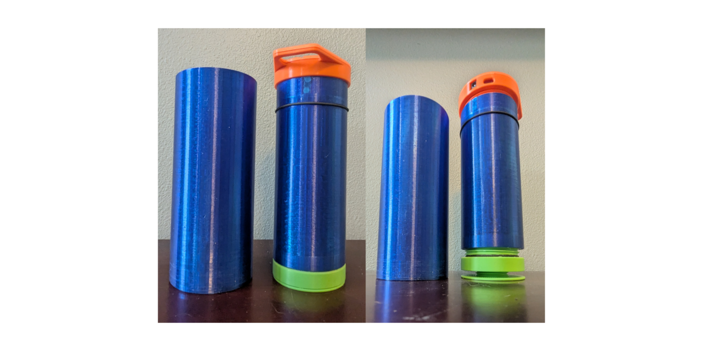
The initial/minimal prints for the inner bottle chamber and lid are done! The Unbound branch of the Meridian library, in Idaho, is an incredible place, and I learn something from their knowledgeable staff every time I visit. They’re all wonderful to work with.
The prints looked nice, and I was happy to find that the threading was snug. Since these initial prints were designed for our perfboard electronics, you won’t see the custom PCB we designed in the following three images/clips:


There were, however, a couple of noticeable flaws in our design:
- As I’d feared, the pocket created for the safety magnet was really thin, and gaps in the PETG filament broke through to the female threading of the inner chamber in a certain spot. So we’ll address this in the mechanical revisions to follow.
- While the parts integrated well, I can do better than two-part epoxy for attaching electrical components and for sealing the overall lid enclosure. It’s probably not a good a habit to rely on epoxy for serviceability reasons anyway, so moving forward, I’ll make use of M2 screws.
At this point, the semester has ended, so I’m going to take the remainder of this project to refine the initial CAD parts, add the outer chamber and filter cartridge components, hopefully validate our device’s effectiveness, and compare/contrast with our Product Requirements.
To do so, I first added a UVC transmissible glass lens, before realizing that the pressure exerted on the inferior lid through the filter (Not yet added in the following image) might crack a lens this wide:

So, instead of an incredibly wide lens, I decided to use a small lens with an even smaller hole where the UVC LED PCB can be mounted with M2 screws from inside the lid. To clarify, the rightmost shot of the following image is a cross section:

I added light pipes for our three LEDs, but I’ll have to read more about when they’re the right choice, because so far I’ve heard many mixed opinions about them:

Deviating from the Grayl GeoPress, the filter cartridge I designed is based on the open source Faircap Filter, where a refillable chamber can be packed with cotton, activated carbon + salt, and then more cotton. This is really intended to be a first pass at the filtration stage:

Below, an exploded view depicts all components involved in this build:

For specific dimensions, here are the 2D drawings. You may have to “Open image in new tab” to see the lower level annotations (Also posted on this project’s GitHub page):


I’ve probably overlooked critical details required to make a design like this function, but the best way to learn is to print it all out and see where we’re at! We’ll also still have to “Pretend”, so to speak, since this will be printed in PETG filament, which is not food- or water-safe, nor is it water tight. That said, I’ve sent these out to my library for printing, and we’ll gain some understanding of how we did soon:)
Status & Remaining Barriers
At this stage, I feel good about the control/power direction of the prototype. On the electrical side, I’ve validated the charger/power-path behavior, established a stable 3.3 V rail for the MCU, and confirmed that the UVC branch can be gated safely under firmware control prior to committing to that custom PCB. The first 4-layer board also populated and powered up without any major surprises, which gave me confidence that the core control architecture is viable.
What remains is less about whether I can switch and power the system, and more about whether the full bottle can become a safe, manufacturable, and meaningfully validated product.
At this point, the remaining barriers I see are:
- Sanitary drinking path:
- Our current design does implement the filtration stage before the UVC treatment stage, but it requires users to sip from the brim, which still isn’t sanitary. Because of this oversight, we’ll want to design a spout & air hole into our lid, and (possibly) fabricate a PCB that accommodates for these components.
- The current PETG prints are useful for fit checks and mechanical learning, but they are not food-safe, not water tight, and are not appropriate for a true drinking-water prototype in their current form. We’ll want to find an affordable way to create a food-grade metallic prototype in the next iteration.
- Material / mechanical feasibility:
- The o-ring, currently situated on the upper/outer portion of the inner chamber actually needs to be toward the bottom, ideally moved to the outer surface of the filter component. As it currently stands, that o-ring is only forcing the fluid through the bottom of the filter into the inner chamber when the inner chamber has completed 7/8 of its range of motion.
- The thin magnetic pocket, wide-lens concept, and reliance on epoxy all exposed weaknesses in the first mechanical direction. Moving toward smaller optical windows, M2-fastened assemblies, and revised lid geometry will probably improve our design’s robustness and serviceability.
- Final validation:
- Once we’ve addressed the problems above, we’ll need to validate the combined device against the product requirements and testing plan.
So at this point, I’d describe the project as a promising control/power prototype with early mechanical proof-of-concept work completed, but with important sanitary, material, and validation questions still open.


[This page is still under construction, check back soon:) – – 04/09/2026]
Testing & Validation Plan
[I wrote the following testing plan in anticipation of validating our prototype. Once we’ve addressed the remaining design barriers, we’ll test it!]
(Proposed) UVC Testing Methods
Taking the review of design studies, EPA guidelines, and other research into account, what follows is a step-by-step, reproducible means of testing the prototype’s UVC water-treatment effectiveness.
Objective & Overview
Purpose
The purpose of this test is to determine if the prototype provides sufficient water treatment by measuring the log-reduction value (LRV) it achieves using a selected challenge organism under defined conditions and operating modes. Our operating points (container geometry, mixing/static runs, and cycle choices) are patterned after a recent UVC LED container comparison study. The layout of testing sections, logs, and tables mirrors a teaching-lab template for clarity and repeatability.
Acceptance Criteria
- Target log-credit: Viruses, 4-log10
- Required dose: DReq = 186 mJ/cm2
- Acceptance: DVal ≥ DReq. Iterate design until satisfied.
Calculations (To report in the ‘Results’ section of a lab write-up)
- In a collimated-beam test, LRV = k(λ) × Fluence. In this device test, we can’t easily measure the true fluence accumulated. Instead, we’ll measure LRV, then map it back to a referenced collimated-beam equivalent of our observed reduction: RED = LRV / k(λ). Specifically, the referenced part of this calculation will be our k(λ) value (cm²·mJ–1 , published, wavelength- and organism- specific slope linking fluence to inactivation). We will report the obtained RED value in mJ/cm2.
$$\mathrm{LRV}=\log_{10}\left(\frac{N_0}{N}\right)$$
$$
\mathrm{RED}=\frac{LRV}{k(\lambda)}
$$
- To validate RED against our EPA target, we will compute the validated dose (DVal = RED ÷ VF) achieved by our test, and compare DVal to the EPA’s 186 mJ/cm2 required dose (DReq) for 4-log10 viral inactivation credit eligibility (DVal ≥ DReq). We set VF from worst-case test runs and documented uncertainties so that DVal = RED/VF still meets the requirement under worst-case conditions. Missing this mark means iterating on our prototype until our DVal exceeds this DReq threshold.
$$
D_{\mathrm{Val}}=\frac{\mathrm{RED}}{\mathrm{VF}}
$$
$$
D_{\mathrm{Val}} \ge D_{\mathrm{Req}} \
$$
Materials
- Water, Organisms, Reagents
- Water matrix
- Dechlorinated, particulate-free water (or lab DI/RO) adjusted to our intended UVT range. Record temperature.
- Biodosimeter (Viral surrogate)
- Challenge Organism (Biodosimeter): MS2 coliphage
- Host: E. coli (DSMZ 5695 or equivalent)
- Buffers & media
- Tris-MgSO₄ buffer (e.g. 2.5 g/L Tris; 0.6 g/L MgSO₄; pH ≈ 7.3).
- ATCC 271 broth (or TSB) for host growth (with CaCl₂ per method).
- Soft agar (top agar) for double-agar layer (DAL) method.
- TSA/Tryptic Soy Agar plates for bottom layer.
- Sterile saline or buffer for ten-fold serial dilutions.
- Optional: Streptomycin (per method), CaCl₂ supplement for host (per method).
- Water matrix
- Prototype & Instrumentation
- Device Under Test (DUT)
- Prototype UV-C bottle/lid assembly (with all safety interlocks enabled).
- Any mixing hardware the product requires (e.g. magnetic stir bar, slow rocking cradle), if part of the intended use.
- Spectroscopy & UV metrology
- UV-Vis spectrophotometer that covers 200-300 nm (e.g. 1 cm quartz cuvette) to measure UVT at the LED(s) emission peak.
- Optional: UVC photodiode/radiometer (265-280 nm, cosine-corrected) for verifying wavelength emission (not used to compute RED).
- Device Under Test (DUT)
- Microbiology
- Micropipettes (P10, P200, P1000) + sterile tips
- Sterile 15/50 mL conical tubes, sterile 1.5-2 mL tubes
- Sterile 100-1000 mL bottles with caps for sampling
- Water bath (≈45-55 °C) for soft agar
- Incubator (37 °C)
- Vortex mixer
- Colony counter or marking pen & counter app
- General
- Calibrated timer & lab notebook or data sheets
- Labels for every container and dilution
- Cooler/ice packs if transporting samples
- PPE & Safety
- UV-blocking eyewear/face shield (rated for 200-280 nm), lab coat, gloves.
- Use the DUT with lid interlocks engaged and an external blackout sleeve or test box.
- Follow BSL-1 practices for MS2. Disinfect waste with 0.25 L bleach per 10 L test water (≥ 20 min contact), then rinse containers x3.
Glassware & Apparatus
- Sterile sampling bottles (≥250 mL), 4 per operating point (N₀, N, + spares)
- Quartz cuvette (1 cm path) for UVT
- Graduated cylinders (50-1000 mL) for fill-volume accuracy
- Magnetic stir bar + plate or controlled rocking cradle (if “mixed” runs are in scope)
- Marker + labels for matrix, run-ID, time, dilution, replicate
- Waste container labeled “MS2 + bleach”
Procedure
Do not work out of stock bottles. Pre-dispense into labeled secondary containers. Do not cross-contaminate pipettes/tips. Maintain aseptic technique.
- Define Test Matrix
- Operating points (Test-run conditions)
- Nominal:
- UVTNom , nominal fill volume (VNom), nominal LED setpoint, room temp (≈ 20-22 °C), gentle mixing if that is part of intended use.
- Worst-case envelope:
- Lowest UVT to be claimed (UVTMin), max fill volume (VMax), no mixing, minimum optical output expected in normal use.
- Nominal:
- Cycle times (t)
- Choose 4 durations bracketing the intended exposure cycles (0.025 hr, 0.25 hr, 0.5hr, 1 hr)
- Replicates: n ≥ 3 per operating point
- Controls
- Process control (Identical setup, LEDs OFF)
- Sterility control (Water + media only)
- Host control (host + media, no phage)
- Full matrix to be recorded before starting
- Operating points (Test-run conditions)
- Instrument Checks (daily)
- Verify spectrophotometer wavelength calibration & baseline.
- Measure UVT of the water at the DUT emission peak (use quartz cuvette). Record UVT1cm,λ and temperature.
- Prepare Microbiology (day-of)
- Grow E. coli host to log phase (per method)
- Warm soft agar in a 45-50 °C water bath.
- Prepare serial-dilution tubes (1:10 series, 10⁰ to 10⁻⁷).
- Target N₀ ≈ 10⁸ PFU·mL⁻¹ in the bottle to keep plaque counts in range after treatment.
- Spike & Pre-Mix (each test-run)
- Fill the bottle to the defined volume (e.g. 1.00 L ±1%). Record volume and temperature.
- Spike with MS2 to target N0. Cap and mix 30 s (or per product directions).
- Immediately withdraw a pre-dose sample (“N₀ sample”), label, and hold on ice if needed.
- For static runs, allow 30 min to settle [5]. For mixed runs, proceed without settling.
- Light Exposure Stage (the device cycle)
- Ensure UV safety (interlocks, blackout sleeve).
- Run the DUT for the specified cycle time (t)
- Use a calibrated timer.
- For mixed runs, keep the mixing constant across replicates (e.g. rocking at 10 rpm).
- Post-Dose Sampling & Dilutions
- At time (t) of completion, mix gently, then withdraw the post-dose sample (This is our “N sample”).
- Perform ten-fold serial dilutions to 10⁻⁷ as needed.
- Double-agar layer (DAL) plating: for each dilution, combine host + sample in soft agar, pour onto TSA plate, let solidify.
- Incubate inverted at 37 °C for 10-20 h in a humidified bag.
- Controls (Each day)
- Run process controls (same container schedule, LED OFF).
- Plate sterility & host controls to confirm no background plaques or contamination.
- Count, Reduce Data, and Compute RED/DVal
- Count PFU for plates with 10-400 plaques. Average duplicates at the same dilution.
- Back-calculate N₀ and N (PFU·mL⁻¹)
- Compute LRV for each replicate: log10(N0/N)
- Map to RED using the organism- and wavelength-matched collimated-beam (CBA) slope k(λ) (units cm2/mJ): RED [mJ/cm2] = LRV*k
- Use a published MS2 LED CBA slope (k) that matches your emission (e.g. 265-285 nm) and water matrix assumptions. Document the source and any spectral matching you did to choose
- For each operating point, report the mean RED, standard deviation, and 95% CI across replicates.
- Derive and Apply VF (Validation Factor)
- Document and combine identified uncertainties/biases into a multiplicative VF so that the worst-case validated dose still meets requirement. Grade conservatively in the interest of identifying DUT flaws:
- Slope/fit uncertainty in k(λ)
- Spectral mismatch (LED peak/band vs. CBA wavelength)
- Matrix mismatch (UVT drift from nominal during runs)
- Reactor variability (mixing state differences, fill-level tolerance)
- Optical output tolerance & thermal drift (LED bin/aging, cap temperature).
- Analytical variability (plating/replicate CI)
- Document and combine identified uncertainties/biases into a multiplicative VF so that the worst-case validated dose still meets requirement. Grade conservatively in the interest of identifying DUT flaws:
- Compute a conservative VF ≥ 1 (product of the above terms, or equivalently divide RED by each). Then: DVal =REDVFDVal =REDVF
- Use the worst-case operating point.
- Accept if DVal ≥ 186 mJ\cm2. If not, report this in lab notes for future design revisions (Optical power, optics, mixing, or cycle time).
- Report Validated Operating Envelope
- Publish the tested bounds that define safe claims:
- UVTMin (as measured at the device’s emission peak)
- VMax (max fill volume)
- Mixing: at least as effective as the tested mode
- LED output: ≥ the tested setpoint (consider temperature-limited cases)
- Cycle time: ≥ the validated time (t)
- Cleanup & Waste
- Add 0.25 L household bleach per 10 L spent test water; hold ≥ 20 min, then drain.
- Triple-rinse containers. Autoclave or bleach-soak small disposables per BSL-1 SOP.
Data & Calculations (For lab write-up)
Reported tables will contain the following collected data.
- Run log:
- Date
- Operator
- UVT(λ)
- Volume
- Temperature
- LED setpoint
- Mixing mode
- Cycle time
- Replicate ID
- Counts:
- Dilution
- Plate 1
- Plate 2
- Mean PFU
- Calc. PFU·mL⁻¹
- LRV per replicate
- RED per replicate, then mean ± SD (95% CI)
- VF breakdown (list factors and their values, product = VF).
- Validated dose (DVal) and pass/fail vs. 186 mJ·cm⁻² required does (DReq)
Reflection
[To be continued, check back soon!]
- Did we achieve each of our Product Requirement benchmarks?
- Is the device effective and useable?
- How much did it cost?
- What are the remaining critical design flaws / TODO items?
Glossary
Definitions
Fluence (Dose, Radiant Exposure), H: Total UV radiant energy incident per unit area.
$$[H]=\left[\frac{\mathrm{J}}{\mathrm{m}^2}\right]$$
Fluence Rate (Irradiance), E(t): UV power per unit area (Energy per time per area).
$$[E(t)]=\left[\frac{\mathrm{W}}{\mathrm{m}^2}\right]=\left[\frac{\mathrm{J}}{\mathrm{s}\cdot\mathrm{m}^2}\right]$$
Fluence-Irradiance Relationship: Dose is the time integral of irradiance.
$$H=\int_{0}^{t}E(t)\,dt$$
Log Reduction Value (LRV): Log-scale measure of microbial inactivation based on pre/post counts.
$$\mathrm{LRV}=\log_{10}\left(\frac{N_0}{N}\right)$$
Reduction Equivalent Dose (RED): The equivalent fluence a reactor appears to deliver under a specific biodosimetry organism and test condition, inferred by mapping measured LRV back through a published dose-response curve. (In this writeup, RED is treated as an equivalent dose in J/m².)
$$[\mathrm{RED}]=\left[\frac{\mathrm{J}}{\mathrm{m}^2}\right]$$
k-value, k(λ): Slope of the (Approximately log-linear) dose-response relationship at wavelength λ for a given organism (Typically derived from collimated-beam data).
$$\mathrm{LRV}=k(\lambda)\cdot \mathrm{RED}$$
$$\mathrm{RED}=\frac{\mathrm{LRV}}{k(\lambda)}$$
$$[k(\lambda)]=\frac{\mathrm{LRV}}{\mathrm{J}/\mathrm{m}^2}=\frac{\mathrm{m}^2}{\mathrm{J}}$$
Biodosimetry: Using a safe surrogate organism (“Challenge organism”) to infer delivered dose by measuring biological response (LRV) and converting it to RED via the organism’s dose-response curve.
Challenge organism (Biodosimeter): The surrogate microbe used during validation tests (e.g. MS2). Choice matters because each organism has a different dose-response (Different k-values).
Target pathogen: The real-world organism you’re designing to control (e.g. viruses relevant to drinking water). The challenge organism is the test proxy, and the target pathogen is the design intent.
Collimated Beam (CB) testing: A standardized lab method to generate dose-response curves (LRV vs dose) under controlled irradiation, used to derive k-values.
Dose-response curve: Relationship between dose and inactivation. Curves can show nonlinearity (e.g. “shoulders” at low dose, tailing at high dose), so k(λ) is treated as an applicable slope over the operating range.
UV Transmittance (UVT): A key water-quality driver. Lower UVT (Higher turbidity/absorption) reduces delivered dose in the water volume and increases required exposure/optical power.
Validation Factor, VF: A conservative derating factor (VF ≥ 1) used to discount measured RED to a conservative validated dose.
$$D_{\mathrm{Val}}=\frac{\mathrm{RED}}{\mathrm{VF}}$$
Larger VF means more conservatism (Accounts for UVT variability, aging/fouling, hydraulics/mixing, sensor uncertainty, etc.).
Required Dose, DReq: The dose required for a chosen log-credit target (e.g. 4-log virus).
Validated Dose, DVal: The conservative dose you are allowed to claim after applying VF to a measured RED.
EPA log-reduction credit criterion: Pass/fail condition for credit:
$$D_{\mathrm{Val}} \ge D_{\mathrm{Req}}$$
Key Design Parameters
- Target credit: 4-log virus (conservative disinfectant performance target)
- EPA required dose: $$D_{\mathrm{Req}}=186\,\frac{\mathrm{mJ}}{\mathrm{cm}^2}$$ $$1\,\frac{\mathrm{mJ}}{\mathrm{cm}^2}=10\,\frac{\mathrm{J}}{\mathrm{m}^2}\;\Rightarrow\;186\,\frac{\mathrm{mJ}}{\mathrm{cm}^2}=1860\,\frac{\mathrm{J}}{\mathrm{m}^2}$$
- Chosen validation factor (derating): $$\mathrm{VF}=\langle\text{insert value}\rangle$$ Rationale: worst-case UVT, LED aging/fouling, mixing/orientation, sensor/calibration uncertainty, and other test-to-field gaps.
- Design-equivalent dose requirement (before VF derating): $$\mathrm{RED}_{\mathrm{Req}} = D_{\mathrm{Req}}\cdot \mathrm{VF}$$
- Target cycle time (UX-driven): $$t_{D_{\mathrm{Req}}}=\langle\text{insert: 30 s / 3 min / etc.}\rangle$$
- Implied optical/geometry requirement (average effective irradiance): $$E \approx \frac{P_{\mathrm{opt}}}{A_{\mathrm{eff}}}$$ $$\mathrm{RED}_{\mathrm{Req}} \approx E\,t_{D_{\mathrm{Req}}} \;\Rightarrow\; \frac{P_{\mathrm{opt}}}{A_{\mathrm{eff}}} \approx \frac{\mathrm{RED}_{\mathrm{Req}}}{t_{D_{\mathrm{Req}}}}$$
- Worst-case assumptions to state up front: UVT (turbidity), LED thermal droop, aging/fouling of optical surfaces, orientation (“dark zones”), and mixing state (stagnant vs. shaken/flowing).
Math Clipboard
$$
\text{Fluence} = \int (\text{Fluence Rate}) \, dt
$$
$$
\frac{\mathrm{J}}{\mathrm{m}^2} = \int \left[\frac{\mathrm{W}}{\mathrm{m}^2}\right] dt
$$
$$
H = \int E \, dt
$$
$$
\mathrm{LRV} = \log_{10}\!\left(\frac{N_0}{N}\right)
$$
$$
\mathrm{LRV} = k \, (\mathrm{RED})
$$
$$
[\mathrm{RED}] = \frac{\mathrm{LRV}}{m^{2}/\mathrm{J}} = \frac{\mathrm{J}}{m^{2}}
$$
$$
\mathrm{RED} = \frac{\mathrm{LRV}}{k}
$$
$$
[k] = \frac{\mathrm{LRV}}{\mathrm{J}/m^{2}} = \frac{m^{2}}{\mathrm{J}}
$$
$$
k = \frac{\mathrm{LRV}}{\mathrm{RED}}
$$
$$
D_{\mathrm{Val}} = \frac{\mathrm{RED}}{\mathrm{VF}}
$$
$$
D_{\mathrm{Val}} \ge D_{\mathrm{Req}}
$$
$$
t \propto \frac{1}{P_{\mathrm{opt}}}
$$
$$
P_{\text{Remaining Optical}}
=
P_{\text{Electrical Input}}
\cdot
\frac{100 – \%\text{Input Power Lost As Heat}}{100}
$$
$$
k(\lambda)
$$
$$
D_{\text{req}} = \text{required fluence (dose)}
$$
$$
D_{\text{design}} = D_{\text{req}} \cdot VF
$$
$$
D_{\text{design}} = \frac{D_{\text{req}}}{VF}
$$
$$
\mathrm{LRV}_{\text{design}} = k(\lambda)\,D_{\text{req}}\,VF
$$
$$
D_{\text{req}}\,VF = \frac{\mathrm{LRV}_{\text{design}}}{k(\lambda)}
$$
$$
\bar{E} \approx \frac{P_{\text{opt}}}{A_{\text{eff}}}
$$
$$
D_{\text{design}} = \bar{E}\,t
$$
$$
t = \frac{D_{\text{design}}}{\bar{E}}
$$
$$
t = (D_{\text{req}})(VF)(A_{\text{eff}})\left(\frac{1}{P_{\text{opt}}}\right)
$$
$$
t = \left(\frac{\mathrm{LRV}_{\text{design}}}{k(\lambda)}\right)\,(A_{\text{eff}})\left(\frac{1}{P_{\text{opt}}}\right)
$$
$$
\frac{\mathrm{LRV}_{\text{design}}}{k(\lambda)} = t\,\frac{P_{\text{opt}}}{A_{\text{eff}}}
$$
$$
k = \frac{\mathrm{LRV}}{\mathrm{RED}}
$$
$$
t \propto \frac{1}{P_{\text{opt}}}
$$
$$
t \propto \frac{A_{\text{eff}}}{P_{\text{opt}}}
$$
$$
A_{\text{eff}} = \frac{P_{\text{opt}}}{\bar{E}}
$$
$$
\mathrm{LRV}=\log_{10}!\left(\frac{N_0}{N}\right)=k(\lambda)\cdot \mathrm{RED}
$$
$$
\mathrm{RED}=\frac{\mathrm{LRV}}{k(\lambda)}
$$
$$
D_{\mathrm{Val}}=\frac{\mathrm{RED}}{\mathrm{VF}}
$$
$$
D_{\mathrm{Req}}=186\,\frac{\mathrm{mJ}}{\mathrm{cm}^2}
$$
$$
D_{\mathrm{Val}} \ge 186\,\frac{\mathrm{mJ}}{\mathrm{cm}^2}
$$
$$
D_{\mathrm{Val}} \ge D_{\mathrm{Req}} \, ?
$$