There are future improvements planned for this project, but in case it helps someone out, here is my progress. It’s also good practice in retaining what I’ve learned, which has been quite a lot.
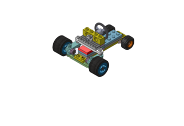
First of all, this is what we’ll build in “Part 1”:
Initial Idea
Having spent some time learning the basics of C/C++, Arduino IDE (Integrated Development Environment), various software libraries, and the core concepts of circuit design, I was otherwise new to the maker community. Working through the Notes & Volts’ Teensy Synth tutorial series (Parts 1-9) was also a big help in understanding the role of development boards in this process. To paint a picture of what I’m trying to accomplish with this project, here is a use case, or general pain point, from a potential user’s point of view:
“I’m going about my business, engaged in various activities while listening to music. Half aware of a song pulsing in the background, I begin to drift through measures of its heavy swung backbeat, playing with meter and phrasing, fingers counting in sets of eight or sixteen against one knee. Isn’t it funny how we have four fingers? They have a mind of their own sometimes. If I had sensors wrapped around my finger tips, they could be my sketchpad! Arriving at my studio, I’d import the constructed patterns into my PC for use within production software. The sensory data could then be substituted with sounds of higher fidelity, and sounds of various length (e.g. staccato vs. marcato) would then be auditioned, as the attribute of a sound’s duration tends to affect a pattern’s overall feel.”
– Potential User
If we prefer something more direct, here is that same sentiment distilled down to a user story:
“As a creator who is busy with life’s daily challenges,
I need to quickly and accurately sketch out my ideas without imposing on other activities
in order to build upon them once I return to my studio.”
– Potential User
To address this desire, I’ve made it my goal to craft a standalone, wearable drum sequencer on which MIDI data can be recorded with nothing but a set of fingertips, and a relatively hard surface. Super niche right? I agree, but hear me out. It’s only natural that many of us enjoy participating in the act of creation, and if music happens to be an outlet for you, maybe this wearable can help you save time, and pun intended, to not miss a beat.
Discovery
The discovery phase of this project involved some due diligence in searching for a similar device to ensure I wasn’t re-inventing the wheel. I found many similar products in both the commercial and DIY domains, none of which quite met the needs of our user. The examples outlined below make use of a glove form factor, which is where I intend to take the design once I’ve condensed the modular components into a PCB.

The first product of “near-fit” are the Mi.Mu Gloves. I’m an avid admirer of Imogen Heap’s music, but that’s not why they’re worth mentioning. Instead, it’s because they’re wearable, include wireless functionality, and can communicate via MIDI (Musical Instrument Digital Interface) – all of which are features I need. As a quick side note, MIDI is a communication protocol used to synchronize audio to video, control stage lighting, and is arguably the dominant digital standard used on the performance side of music composition. So the Mi.Mu Gloves are marketed as a music production tool focusing on this performance aspect (think of a flutist’s breathing cadence or a cellist’s nuanced bow strokes), and also capitalize on existing sensor technologies, including flex sensors, accelerometers, magnetometers, and gyroscopes.
While the best resource I’ve found for DIY wearable gadgets and e-textiles is Kobakant’s “How To Get What You Want” , Mi.Mu Glove’s product overview page serves well as gateway learning resource for upper-extremity, wearable tech. These gloves also make use of an IMU (Inertial Measurement Unit), which is an alternative (maybe additional?) design consideration I’ve entertained repeatedly throughout the course of this project.

Mi.mu has also developed a suite of tools that orbit the core glove product: A corresponding desktop software, mobile app that functions as a motion controller, and a VST (Virtual Studio Technology) capable of granular synthesis. They call these Glover, Gliss, and Jellyfish respectively. That’s all groovy jazz and what not, but they aren’t quite “standalone”, that is, they require the use of some form of a DAW to operate. That’s a deal breaker for me, since my goal is to enable meaningful music creation under circumstances that specifically lack DAW access.
Another related, and by far flashiest, template product are Manus’s Quantum Mocap Metagloves. They aren’t tailored for musical expression specifically, but they are a beast in their own right – capable of tracking finger movement with sub-millimeter resolution, and they also function wirelessly. They also may not have an IP rating (Ingress Protection Rating), but their fingerless, ruggedized look is an aesthetic bar I’ll strive to meet. More importantly, their finger-sleeve design offers a promising means of fastening sensors to fingertips, which might strike a balance between stability and ergonomics.

You’ll also see me draw on certain elements from two additional DIY projects, both of which are great resources for designing upper extremity wearables. One is Zack Freedman’s “Somatic” glove, which uses machine learning to turn hand gestures into text, among other things. The other is Francisco Correia’s MIDI glove, which provided lots of relevant insight, but couldn’t save MIDI data for later use. It does, however, offer a strategy that contrasted the Manus gloves for mounting sensors to phalanges: Dorsally mounted piezoelectric sensors. More on that later.
Goals & Requirements
Development Plan
To break down the challenges involved in bringing this device to life, I made a quick development plan partitioned by function:
INPUT
· 4 velocity sensitive inputs serving as fingertip sensors (Force-sensing resistors, piezoelectric, or flex sensors)
· User input / transport controls consisting of at least Record, Play, and Pause (Buttons and/or encoders that must be mechanically accessible on the user interface)
· Additional controls to create, adjust length of, and toggle between patterns
FILE STORAGE
· Save MIDI patterns in SMF (Standard MIDI File) format for universal file readability
· Store user-sequenced material to microSD card, or some other common form of removable or transmittable storage
PROCESSING
· Microcontroller or programmable logic controller to process data and mediate between input & output
REC / SEQUENCING
· Keep time w/o external clock signal
· (Add-on?) Toggle quantize on/off
· Variable tempo & time signature controls
· (Add-on?) Microcontroller acts as USB Host device as opposed to client device
FORM FACTOR
· Wearable enclosure comfortably mounts to dorsal side of hand (or wist) and causes no interference with upper limb anatomy
· Distal attachment of finger sensors must be non-intrusive & reliable
· Proximal attachment of sensors to device must be removable (i.e. detach gracefully if tugged or yanked on)
OUTPUT
· Trigger MIDI output to storage device & USB connection
· Simultaneously produce audio output via discrete speaker module & auxiliary jack
GUI DISPLAY
· Provide visual representation of what user is playing, sequencing, and saving (LED indicators later to be replaced by graphical LCD, OLED, TFT, or capacitive touch screen display)
POWER
· Li-po battery to power device when unplugged
· Safe battery charging / power management
· Switches between USB & battery power
So to reiterate, our primary goal is to capture recordings of percussive patterns with no computer in sight, and to later open these pre-cooked patterns on a computer for further editing and auditioning of various sound samples.
Input
Like afferent neurons, which deliver information about the environment to our brains, we’ll need some kind of pressure-sensitive peripheral. Specifically, we need to find a way to translate this physical finger-tapping action (analog) into a language our microcontroller understands (digital).
To this end I considered a few different sensor types, including flex sensors, piezoelectric vibration sensors (piezos), and force-sensing resistors (FSRs). While flex sensors would be great if we needed to measure degrees of finger motion (and by extension in assisting limb function in victims of neurotrauma), I figured getting these to detect a tapping motion could quickly devolve into verbose software handling and convolute our main objective. One downside of piezo sensors is that they might pick up accidental readings when we bump into things. FSRs on the other hand, require a fairly specific force to detect what we’re looking to measure. They’re also about 0.45mm thick (much thinner than piezos) so they seem like the more sensible choice for ergonomic wearables. Since accuracy of the sensor readings, and both comfort and weight of the device are important factors, I’ve chosen to go with the FSR 402 sensor by Interlink. We’ll have to devise a sturdy means of mounting these to our fingertips, but we’ll kick that can down the road until we’ve got the software and circuitry cooperating.
I also plan to incorporate additional user input controls to give our user more flexibility in how they interact with the device. These will include 3-12 momentary push buttons and a PEC11R rotary encoder for variable tempo control and/or track seeking.

Processing
For this project’s central nervous system, I wanted to use an easily programmable development board with plenty of I/O pins and a hearty clock speed. I had considered the Arduino Due and HiLetgo’s ESP-WROOM-32, but ultimately landed on PJRC’s Teensy 4.1 microcontroller, and here’s why:
- It has 18 analog pins, 55 digital input/output pins, and 8 serial UART ports, which is likely more than enough for our user input controls, display, and four finger sensors.
- It’s supported by Teensyduino, which is a software add-on allowing us to program it within the Arduino IDE, and provides a ton of example sketches to learn from.
- Its processor, an ARM Cortex-M7, has a relatively rapid clock speed of 600Mhz, which is over twice as fast as the Due, and is 360Mhz faster than the ESP-WROOM-32’s top speed.
- It has 8MB of flash memory, and provides access for soldering an additional 8MB PSRAM chip (for large buffers or variables) and/or a flash memory chip (for non-volatile storage)
- It has hardware for interfacing with a microSD card built in, which means I won’t have to worry about interfacing a separate hardware component for file storage.
Another reason I chose the Teensy is because many of the projects shared by PJRC forum users are intensely inspirational, and it’s pretty beautiful this kind of educational resource exists.

Audio Output
For audio output, I’m using PJRC’s Rev D2 Audio Shield for its compatibility with the Teensy microcontroller, and its forum support also lightens my load of troubleshooting (most issues you encounter have been discussed at length with code examples, oscilloscope charts, and equipment comparisons). The audio shield contains an SGTL5000 low power stereo codec, which will receive I2S stereo data from the Teensy, and pass it through to our amplifier and speaker in order to produce an analog output signal. We’ll be using the audio shield’s stereo DAC to drive headphone and line output. Note that the audio shield will also handle LINEIN, MIC_IN, and digital I/O if needed.


The last stop our audio signal makes before becoming air-borne, acoustic energy is the Adafruit STEMMA Speaker module. It includes a PAM8302A 2.5W Class-D mono audio amplifier and a 1 Watt, 8 ohm speaker. It’s got three enormous pads labelled GND, POWER, and SIGNAL — The last of which I have receiving signal from the audio shield’s “line-out”. For the upcoming proof of concept, I’m skipping the discrete speaker module altogether, and will just send audio straight out the 3.5mm audio port to a home stereo.

MIDI Output
The MIDI output’s final destination will be some form of digital storage, probably a microSD card. But for now I’ll have the Teensy produce instructions for USB MIDI, and check for a response on my laptop.
(Tentative) GUI Display
This option will likely be a later addition. I think that having a modern means of navigating menus/modes/files on the device is incredibly important for many gadgets nowadays. However, our user story doesn’t necessitate a screen-style display, so I’m going to wait until we have the basic functionality nailed down before committing to anything beyond indicator LEDs.
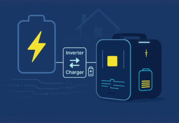
Power Management
Learning about batteries and power management has been a blast so far, and if this topic were Mt. Everest, I’d probably still be lacing my boots up in preparation for a trek to base camp. Anyhow, we obviously need our device to run on battery power, for which I’ve selected a 3.7V, 2000mAh lithium-ion polymer battery. “Li-po”, you say? Piece of cake, right? Not exactly. We still need to implement proper charge controlling and voltage regulation for switching between power supplies, battery charging, and to delivering proper power specifications to our load.
Nearly every resource I’ve listened to places a heavy emphasis on the temperamental nature of these batteries. While many commercial li-po packs are sold with an embedded BMS (Battery management system), it’s definitely not enough to make this thing function safely on its own. And in order to expedite a working proof-of-concept, custom designing a charge controller and step-up conversion circuit will have to wait. I’ll be connecting a li-po battery to the JST connector of an Adafruit 1000C Powerboost, which has a pre-packaged MCP73871 charge controller to babysit our load sharing, and a TPS61090 step-up / boost converter for us.


I noticed a potential rabbit hole on the topic of N-channel & P-channel MOSFETs while selecting this component, which I’ve set aside for learning in the near future. We’ll likely open this can of worms when designing a PCB that accommodates switching power sources between the 5V USB and a nominal 3.7V li-po battery. For now, this temporary solution can keep the power management safe, lightweight, reliable.
For hardware in general, it will be much more space efficient to take what is needed from each modular “off-the-shelf” component listed above, and design a PCB for the circuits ourselves. However, they’re great prototyping tools, and frankly I’m still learning how to design a custom board for fabrication!
Proof Of Concept

I started by laying eyes on what seemed like the three most fundamental functionalities: Input, processing, and output. I wanted to confirm that I could translate mechanical force into an electrical signal, process it, then spit corresponding sound waves and MIDI data out the other end. In doing this now, I figured I’d be gaining enough solid ground to stand on for gaining more traction later. So let’s go!
Breadboarding
After reading about what others had done to interface force-sensing resistors with MIDI communication, I breadboarded the Teensy, audio shield, and four FSR sensors receiving USB power from a laptop. The FSRs used in the next few images aren’t the Interlink 402’s I mentioned, but they served as a stand-in for early prototyping.

FSR Circuit
This involved laying down the circuit for the force-sensing resistors, which works like this: The Teensy microcontroller delivers current from a 3.3V supply pin into one of the tabs protruding from our force-sensing resistor. The other tab is connected to ground through a second 10k resistor, forming a voltage divider circuit. The Teensy’s analog pins monitor voltage between the two resistors. As pressure is applied to the FSR, its resistance decreases, causing the voltage across it to increase (from 0V to nearly 3.3V) in accordance with Ohm’s law. This voltage change can be read from our analog pins, allowing us to measure when and how hard we’re pressing on these sensors.
If you have tips on schematic formatting conventions, my ears are open!

Software 1
Input, Processing, MIDI & Audio Output
The code makes use of the teensy audio library, the wav2sketch utility, and Adrian’s awesome example code for translating mechanical force applied to the FSR sensors into MIDI data. If you’re familiar with C/C++ programming, pardon my stumble-learning, and it’s a good idea to verify with a second source of you’re trying to learn from me:
// Libraries
#include "AudioSampleKickkhronos.h"
#include "AudioSampleHh1khronos.h"
#include "AudioSampleSnarekhronos.h"
#include "AudioSampleHh2khronos.h"
#include <Audio.h>
#include <Wire.h>
#include <SPI.h>
#include <SD.h>
#include <SerialFlash.h>
The “// Libraries” section includes interface .h (header) files we need in order to make various declarations (to functions, classes, variables, etc) throughout our sketch. I remember this by thinking “Hmm… header.. what does a head do? It speaks. It declares“. Each declaration links to a definition located in a corresponding source/implementation .cpp (C-preprocessor) file, which the compiler will subsume into our program when we hit our IDE’s “upload” button. For example, our #include “AudioSampleKickkhronos.h” header file comes from a .wav file I converted into raw audio data using PJRC’s wav2sketch tool. When uploading my program to a microcontroller, the compiler sees the .h file, and looks for the corresponding .cpp file on my laptop’s hard drive containing the raw audio data, and copies it to our sketch folder. Without definitions/.cpp files, our declarations/.h files are hollow; but with them we’re able to trigger audio files stored in Teensy’s internal program memory!
// GUItool: begin automatically generated code
AudioPlayMemory          playMem3;       //xy=248.75,260.0000057220459
AudioPlayMemory          playMem4;       //xy=248.75,325.0000057220459
AudioPlayMemory          playMem2;       //xy=251.25,193.7500057220459
AudioPlayMemory          playMem1;       //xy=256.25,135.0000057220459
AudioMixer4              mixer1;         //xy=498.75000762939453,230.00000381469727
AudioOutputI2S           i2s1;           //xy=735.0000114440918,230.00000190734863
AudioConnection          patchCord1(playMem3, 0, mixer1, 2);
AudioConnection          patchCord2(playMem4, 0, mixer1, 3);
AudioConnection          patchCord3(playMem2, 0, mixer1, 1);
AudioConnection          patchCord4(playMem1, 0, mixer1, 0);
AudioConnection          patchCord5(mixer1, 0, i2s1, 0);
AudioConnection          patchCord6(mixer1, 0, i2s1, 1);
AudioControlSGTL5000     sgtl5000_1;     //xy=433.75000762939453,493.7500057220459
// GUItool: end automatically generated code
I generated the “// GUItool” section with the help of Teensy’s Audio System Design Tool for Teensy Audio Library, which is an intuitive way to plan how data flows through our hardware. The four camel-cased “playMem” nodes will be responsible for passing unique audio data from Teensy’s memory to “mixer1”, which then uses I2S (Inter-IC Sound) to output sound.

In the “// Global Variables” section, we declare our variables. A few different things are being set up here, such as note numbers for our MIDI system, but the main thing is achieving velocity sensitivity.
Analog pins 14-17 are part of our FSR voltage dividing circuit, and here we’re assigning them to an integer array we’ll call “int FSRpin[]…”. This has to do with INPUT, and we’ll use this array to sample readings from each FSR sensor by iterating through a counter variable during “void loop ()”, wherein a 10-bit value between 0 and 1023 (a voltage range of 0 to 3.3V) is assigned to a new integer variable “int FSRRead”. If enough force is applied to an FSR to exceed a certain threshold, that 10-bit value gets an all-expense-paid trip to several exotic locations:
(A) “void NoteOnSend…” to re-map a 0-1023 range of 10-bits to a 0-to-127 range of 7-bits, which is the standard range for MIDI velocity. A Note-On message (0x90 in hex) is then produced containing the parameters (note number, velocity, and channel) we need to specify SMF format MIDI commands.
(B) “void PolyTouchSend…”, which repeats the 0-to-127 remapping business, but uses this number to produce a stream of Polyphonic-pressure MIDI messages (0xA0 in hex). Following an initial Note-on message, this will continue to spew aftertouch commands until our finger pressure drops below a different threshold, namely “int AFTERTHRESH…”. It’s not really necessary for percussion, but if I want to incorporate a synth or sampler feature down the line, having this level of expression will be super rad.
(C) The third remote island our 10-bit value cruises to is “void SampleOnSend…”, where we translate finger pressure into a mixer gain value. This, in turn, triggers the audio samples prepared in the .h and .cpp files earlier, and also dictates the volume of our audio output.
When we reduce our finger pressure back down/below/through the threshold we set, the counter system in our main “void loop ()” produces a MIDI Note-off message (0x80 in hex) without the need for a separate function… at least for the time being. Some MIDI instrument manufacturers get away with not using Note-off commands at all, but we definitely need them if we’re to have hope of writing MIDI files to a microSD card in a format that will be legible within a DAW software.
Here is the input, processing, and MIDI/audio output code in its entirety:
// Libraries
#include "AudioSampleKickkhronos.h"
#include "AudioSampleHh1khronos.h"
#include "AudioSampleSnarekhronos.h"
#include "AudioSampleHh2khronos.h"
#include <Audio.h>
#include <Wire.h>
#include <SPI.h>
#include <SD.h>
#include <SerialFlash.h>

// GUItool: begin automatically generated code
AudioPlayMemory          playMem3;       //xy=248.75,260.0000057220459
AudioPlayMemory          playMem4;       //xy=248.75,325.0000057220459
AudioPlayMemory          playMem2;       //xy=251.25,193.7500057220459
AudioPlayMemory          playMem1;       //xy=256.25,135.0000057220459
AudioMixer4              mixer1;         //xy=498.75000762939453,230.00000381469727
AudioOutputI2S           i2s1;           //xy=735.0000114440918,230.00000190734863
AudioConnection          patchCord1(playMem3, 0, mixer1, 2);
AudioConnection          patchCord2(playMem4, 0, mixer1, 3);
AudioConnection          patchCord3(playMem2, 0, mixer1, 1);
AudioConnection          patchCord4(playMem1, 0, mixer1, 0);
AudioConnection          patchCord5(mixer1, 0, i2s1, 0);
AudioConnection          patchCord6(mixer1, 0, i2s1, 1);
AudioControlSGTL5000     sgtl5000_1;     //xy=433.75000762939453,493.7500057220459
// GUItool: end automatically generated code

// Global Variables
int FSRpin[] = {A17, A16, A15, A14};  // Analog pins connected to FSRs"
const int FSRs = 4;                   // Number of FSRs //
int Note [] = {60, 61, 62, 63};       // MIDI note #'s listed in order of FSRpin
int counter [FSRs];
int VELMASK = 0;
int ATMASK = 0;
int AFTERTHRESH = 50;         // Analog sensor value above which aftertouch messages are sent
int THRESH = 45;              // Analog sensor value above which note / velocity is recognised
int VELTIME = 500;            /* "Counter value at which point velocity is sampled...
                              counter is zero when first touched, velocity is sampled X ticks later
                              500 ticks sounds like a lot, but the teensy LC is clocked at 48Mhz"*/
int AFTERTIME = 2500;         /* "Counter value at which point aftertouch is sampled ...
                              every X ticks of a touch, until released ...
                              you don't want too many aftertouch messages per touch,
                              and 2500 gives a surprising number" */
int MIDIMIN = 20;             // Bottom MIDI value for the MIDI velocity AND aftertouch messages
void NoteOnSend (int);        // One of 3 main INPUT-related functions outside of void setup(); and void loop();
void PolyTouchSend (int);     // One of 3 main INPUT-related functions outside of void setup(); and void loop();

/*
Relating to Wav2Sketch/output audio:
*/
int channel [] = {0, 1, 2, 3};                /* Mixer channels for wav2sketch audio samples, listed
                                              in order of their respective .wav samples & analog pins */
const int SAMPLEs = 4;
int counter2 [SAMPLEs];
void SampleOnSend (int);                      // One of 3 main INPUT-related functions outside of void setup(); and void loop();
void gain (unsigned int channel, float gain); // Function that goes within void SampleOnSend(int); function.
                                              // ...little confusing to set up because the names for second parameter
                                              // "gain" varied as "level" in the ArduinoIDE>TeensyExample sketches
void setup() {
  Serial.begin (32500);
  AudioMemory(10);
  sgtl5000_1.enable();
  sgtl5000_1.volume(0.5);
  mixer1.gain(0, 0.4);
  mixer1.gain(1, 0.4);
  mixer1.gain(2, 0.4);
  mixer1.gain(3, 0.4);
}

void loop () {
  for (int i = 0; i < FSRs; i++) {
    int FSRRead = analogRead(FSRpin[i]);
    if (FSRRead > THRESH) {
      counter[i] ++;
      if (!(VELMASK & (1 << i)) && (counter[i] == VELTIME)) {
        VELMASK |= (1 << i);
        counter [i] = 0;
        NoteOnSend (i);
        SampleOnSend (i);
        }
      if (counter [i] == AFTERTIME) {
        counter [i] = 0;
        PolyTouchSend(i);
      }
    }
    else {                                    // When FSRRead(0-1023) is NOT greater than 45, do this: {...}
      if (VELMASK & (1 << i)) {
        usbMIDI.sendNoteOff (Note[i], 0, 10);
        VELMASK &= ~ (1 << i);
        counter [i] = 0;
      }
    }
  }
}

void NoteOnSend (int j) {
  int FSRRead = analogRead(FSRpin [j]);
  int velocity = map (FSRRead, 0, 800, MIDIMIN, 127);
  usbMIDI.sendNoteOn (Note[j], velocity, 10);
}


void SampleOnSend (int k) {
  analogReadResolution(7);
  int FSRRead2 = analogRead(FSRpin [k]);
  float gain = map (FSRRead2, 0, 127, .2, 1.0);
  mixer1.gain(channel[k], gain);
  if (analogRead(A17) >= THRESH) {
    playMem1.play(AudioSampleHh2khronos); }
  if (analogRead(A16) >= THRESH) {
    playMem2.play(AudioSampleSnarekhronos); }
  if (analogRead(A15) >= THRESH) {
    playMem3.play(AudioSampleHh1khronos); }
  if (analogRead(A14) >= THRESH) {
    playMem4.play(AudioSampleKickkhronos); }
}

void PolyTouchSend (int j) {
  int FSRRead = analogRead(FSRpin [j]);
  if (FSRRead > AFTERTHRESH) {
    int aftertouch = map (FSRRead, 0, 800, MIDIMIN, 127);   //Input of 0-800 just "worked" better. Not sure why yet.
    usbMIDI.sendPolyPressure (Note[j], aftertouch, 10);
  }
}

/*
Citations and Helpful Links:
1-- https://www.pjrc.com/teensy/gui/ --
      "Mixer" Function description listed in the lovely Teensy Audio Design Tool
  gain(channel, level);
  Adjust the amplification or attenuation. "channel" must be 0 to 3. "level"
  may be any floating point number from 0 to 32767.0. 1.0 passes the signal
  through directly. Level of 0 shuts the channel off completely.
  Between 0 to 1.0 attenuates the signal, and above 1.0 amplifies it.
  Negative numbers may also be used, to invert the signal. All 4 channels
  have separate gain settings.
2--https://forum.pjrc.com/threads/31797-Teensy-FSR-based-MIDI-controller--
      THANK YOU Adrian!!! The majority of the code used in this sketch was drafted from Adrian's FSR MIDI sketch
  that can be found at the above link.
3--https://forum.arduino.cc/t/beginners-include-define-declarations-definitions-and-initialisation/539840
      #include, #define, declarations, initialization guide for dummies like me:)
4--https://www.cs.odu.edu/~zeil/cs333/f13/Public/faq/faq-htmlsu21.html#:~:text=The%20short%20answer%20is%20that,difference%20between%20declarations%20and%20definitions.
      header files vs cpp files GREAT simple breakdown
*/
^ The .h/.cpp audio sample files generated by Paul’s Wav2Sketch tool can be found in this repo. If you want to use your own sounds, there’s a guide here.
NOTE: I messed around with threshold values until I was okay with the result. One point of trial and error that took some correction was the scaling between MIDI note velocities and the gain control of our audible output. When we tap out our pattern, we’ll be adapting our finger’s playing intensity to the volume level being output from the speaker. So if the MIDI velocities don’t scale similarly, what we’re hearing isn’t a great gauge of what we’ll eventually be saving to our .mid files. With that ironed-out, here’s a cheesy demo of that point in development:
Now that the input and output processing are working at a basic level, we’ll work on storing MIDI files in SMF format to a microSD card. Later on, we’ll tackle the sequencing aspect so we can record what we’re playing, loop it back for us to hear, and build upon our patterns “on the fly”.
Software 2
MIDI File Storage
With the additional guidance of Pomax’s inline-midi recorder and Nick Gammon’s advice on this theremin project, I had the chance to learn the basics of bit management, and apply it to the basic MIDI protocol running in our project. To set up the recording of MIDI files for later playback on PC, the Mcgill Standard MIDI-File Format Spec and a review of Simon Hutchinson’s The MIDI Protocol: Bits, Bytes, and Binary were also helpful.
Here I’ll attempt an overview of what I’ve done to prepare, manage, and write .mid files to a microSD card. If you’re listening in from behind the wheel of a motorized vehicle, feel free to skip this section because it might put you to sleep.
Status Bytes & Data Bytes
Similar to how an oversized load carries house components and airplane wings via freeway, MIDI messages are packaged in partial-message, 8-bit shipments (Or 32-bit depending on how you view it). Those 8-bits make up a byte, and the highest (leftmost) bit of that byte specifies it as either a status byte (1xxx cccc) or data byte (0### #### and 0vvv vvvv).
In a status byte, we set (turn to “1”) the highest bit, leaving us with 7 bits to work with. The following three “x” bits indicate a specific kind of MIDI message, for instance, a “Note-on” status byte looks like “1001 cccc”. The remaining nibble “cccc” gives us our MIDI channel number 1-16. So a status byte indicating a note-on event over channel 1 reads as “1001 0000” in binary, as shown in the following table:
| Status Byte | |
| status byte indicator | 1xxx cccc |
| note-on | 1001 cccc |
| channel 1 | 1xxx 0000 |
| = 1001 0000 (90 HEX) |
In a data byte, we clear (turn to “0”) the highest bit, which again leaves us 7 bits to work with. Notice how in our previous table we didn’t specify which note was pressed or how hard we pressed it. In my code, the parameters “b1” and “b2” are these data bytes. More specifically, “b1” uses a 7-bit (0-127) range for note number, and “b2” uses the same range for velocity.
So let’s say we play an Eb5 note (75 in decimal), over channel 2, with a velocity of 33. The resulting three bytes will read “91 4B 21” in hexadecimal, which is “10010001 01001011 00100001” in binary. Here’s the table:
| Status Byte | |
| status byte indicator | 1xxx cccc |
| note-on | 1001 cccc |
| channel 2 | 1xxx 0001 |
| = 1001 0001 (91 HEX) | |
| Data Byte 1 | |
| data byte indicator | 0### #### |
| note number | 0100 1011 |
| = 0100 1011 (75 BIN / 4B HEX) | |
| Data Byte 2 | |
| data byte indicator | 0vvv vvvv |
| note velocity | 0010 0001 |
| = 0010 0001 (33 BIN / 21 HEX) |
Header & Track Chunks
Zooming out, we have MIDI files, which are composed of instructional data “chunks”, and are identified by our program as either “MThd” for a header chunk, or “MTrk” for each track chunk that follows. We’ll represent these 4-letter sets in hexadecimal where, as you might’ve noticed, bytes are commonly notated with a prequalifying “0x..” followed by two digits representing a value in ASCII. By coding “0x4D” (1 byte), we’re grabbing an “M” from ASCII, which is the first letter in our header chunk. “… 0x54, 0x68, 0x64” (3 bytes) spells out the rest, yielding “MThd”.
In the following code, we sandwich our header chunk between “byte header[]…” and “…file.write(header, 14)”. A header chunk follows the pattern: <chunk type> <length> <format> <ntrks> <division>
void writeMidiPreamble() {
  byte header[] = {
    0x4D, 0x54, 0x68, 0x64,
    0x00, 0x00, 0x00, 0x06,
    0x00, 0x00,
    0x00, 0x01,
    0x01, 0xD4
  };
  file.write(header, 14);
You may be wondering where in the world the “14” at the end comes from. I’ll do my best to explain, but just to reiterate, I’m still learning so please take this with a grain of salt. We already know each chunk begins with a 4-character ASCII statement, which starts our pattern with a <type> section worth 4 bytes (1 per letter). Following that is a 32-bit, most-significant byte first, <length> section worth another 4 bytes. So far that’s 8 😁. With a <length> section of “0x00, 0x00, 0x00, 0x06”, we’re preparing to write 6 more bytes to our header chunk (00 00 00 06 HEX = 6 DEC). Therefore, a chunk with a <length> section of 6 will occupy a grand total of 14 bytes disk space.
Of the final 6 bytes, the <format> section occupies 2 bytes, and determines the “format zero” MIDI file we’re creating (00 00 HEX = 0 DEC). The <ntrks> section occupies 2 bytes, and determines the number of tracks each track chunk will hold (00 01 HEX = 1 DEC). Lastly, the <division> section occupies 2 bytes, and will specify our method of time keeping. Note that <division> clarifies whether what is called “delta-time” will represent “ticks-per-quarter-note”, or “SMPTE/MTC timecode”. We want to focus on the resolution of musical beat divisions, i.e. “ticks-per-quarter-note”, and SMF convention states that if the highest (leftmost) bit reads “0”, that’s the time keeping method we’ll be selecting (01 D4 HEX = 00000001 11010100 BIN). Picking the proper <division> type will make our .mid files readable inside the DAW software. To summarize the contents of a header chunk, we have: (4 type + 4 length) + (2 format + 2 ntrks + 2 division) = 14 bytes.
In the next piece of code, we sandwich our track chunks between “byte track[]…” and “…file.write(track, 8)”. A track chunk follows the pattern: <chunk type> <length> <MTrk event>+
  byte track[] = {
    0x4D, 0x54, 0x72, 0x6B,
    0x00, 0x00, 0x00, 0x00
  };
  file.write(track, 8);

  byte tempo[] = {
    0x00,
    0xFF, 0x51, 0x03,
    0x06, 0xFD, 0x1F
  };
  file.write(tempo, 7);
}
The <type> section still consists of 4 bytes, as does the track chunk’s <length> section. But our hexadecimal length this time reads “00, 00, 00, 00” which acts as a “placeholder” length since it depends on the duration of our MIDI performance. An <MTrk event> is combination of a timestamp and a MIDI message. The timestamp subdivision is <delta-time>, which is a “variable-length quantity” specifying the distance between a current event and a previous event. Think of the slope formula in algebra. It’s the “x₂ – x₁” operation happening in the denominator, which gives us the distance between those two values. If we do this right, when two notes are played at the exact same time, our <delta-time> will be 0🤞🏽. The MIDI message subdivision inside of our <MTrk event> is the <event> itself, and will contain our status byte and data bytes.
Other important things to note here are that the “+” after the <MTrk event> pattern just means that at least one <MTrk event> must follow our <length>. And just to reiterate, since our <length> is open-ended, the exact number of bytes will vary for track chunks.
Using SMF Spec To Record MIDI Files
So that’s the fundamental function templating a MIDI file for data to be stored in. It starts with a header chunk, and is followed by a series of track chunks. Now the computer will know what to do with the information on the microSD card.
As a quick tangent, I realized while writing this that there are subtle differences in the way certain C/C++ libraries handle MIDI parameters. We’ll be sticking mostly to the <MIDI.h> library by Francois Best, because it has been easier for me to manage when compared to <usbmidi.h>, <MIDIUSB.h>, or <USB-MIDI>. This is mostly due to the way that the note number, velocity, and channel parameters are handled.
With the setup of our MIDI files complete, there are several important processing functions to point out:
void NoteOnSend (int j) {
  int FSRRead = analogRead(FSRpin [j]);
  int velocity = map (FSRRead, 0, 800, MIDIMIN, 127);
  usbMIDI.sendNoteOn (Note[j], velocity, 1);
  myNoteOn(1, Note[j], velocity);
}
The function “void NoteOnSend…” has been upgraded since the code running in the previous demo in order to transmit parameters to a couple of new places. The first transmit “usbMIDI.sendNoteOn…” is just a bonus feature enabling us to use this device as a USB MIDI controller wired to the PC. The second transmit “myNoteOn…” is far more important:
void myNoteOn(byte channel, byte note, byte velocity) {
  writeToFile(NOTE_ON_EVENT, note, velocity, getDelta());
}
This second transmit goes to the function “void myNoteOn(byte channel, byte note, byte velocity)” where we collect the parameters needed for writing SMF format MIDI files. I list the parameters contained in parenthesis because, as I previously mentioned, various functions make use of different MIDI libraries, and not all libraries list MIDI parameters in the same order. It’s critical, for instance, that we’re not writing a velocity data byte to where our computer expects to find a data byte for note number. Moving on, the transmit called “writeToFile…” then passes our parameters along to our next function…
void writeToFile(byte eventType, byte b1, byte b2, int delta) {
  if (!file) return;
  writeVarLen(file, delta);
  file.write(eventType);
  file.write(b1);
  file.write(b2);
}
The “void writeToFile…” function writes three of the four required parameters to a file in the correct order. These three parameters are: One status byte, one data byte for note number, and one data byte for velocity. The odd-man-out here is the “delta-time” parameter, and it will need to be written to our file before the other three. To accomplish this, the transmit “writeVarLen…” sends it to another function to be properly formatted and written to the file. Once that process is complete, our program’s loop returns here to write the other three parameters to the file as well.
/**
   Encode a unsigned 32 bit integer as variable-length byte sequence
   of, at most, 4 7-bit-with-has-more bytes. This function is supplied
   as part of the MIDI file format specification.
*/
void writeVarLen(File file, unsigned long value) {
  // capture the first 7 bit block
  unsigned long buffer = value & 0x7f;

  // shift in 7 bit blocks with "has-more" bit from the
  // right for as long as `value` has more bits to encode.
  while ((value >>= 7) > 0) {
    buffer <<= 8;
    buffer |= HAS_MORE_BYTES;
    buffer |= value & 0x7f;
  }

  // Then unshift bytes one at a time for as long as the has-more bit is high.
  while (true) {
    file.write((byte)(buffer & 0xff));
    if (buffer & HAS_MORE_BYTES) {
      buffer >>= 8;
    } else {
      break;
    }
  }
}
The “void writeVarLen…” function (notation courtesy of Pomax), uses a combination of bitwise operators, bit masking, and bit shifting to arrange our delta-time in such a way that lets us write it to the SMF. The Mcgill spec I linked provides a version of this function on their webpage, and I’m still striving to understand what Pomax has done to modify this into useable C/C++ code. When I do come to grips with it I’ll share what I learn.
So that concludes our sleepy explanation of file storage, and below is the full code up to this point (Pardon my ridiculous use of “//” and “/*…*/” commenting).
// File and MIDI handling
#include "AudioSampleKickkhronos.h"
#include "AudioSampleHh1khronos.h"
#include "AudioSampleSnarekhronos.h"
#include "AudioSampleHh2khronos.h"
#include <Bounce.h>
#include <Audio.h>
#include <Wire.h>
#include <SPI.h>
#include <SD.h>
#include <MIDI.h>
#include <SerialFlash.h>

// INDEX # -->  0     1     2    3
int FSRpin[] = {A17, A16, A15, A14};
const int FSRs = 4;
int Note [] = {60, 61, 62, 63};
int counter [FSRs];
int VELMASK = 0;
int ATMASK = 0;
int AFTERTHRESH = 50;
int THRESH = 45;
int VELTIME = 500;
int AFTERTIME = 2500;
int MIDIMIN = 20;
void NoteOnSend (int);
void PolyTouchSend (int);
//void testingArguments (int);

int channel [] = {0, 1, 2, 3};
const int SAMPLEs = 4;
int counter2 [SAMPLEs];
void SampleOnSend (int);
void gain (unsigned int channel, float gain);

// Our Real Time Clock
#include <RTClib.h>
RTC_DS3231 RTC;
bool HAS_RTC = false;

// Audio pins and values
#define AUDIO 8
#define AUDIO_DEBUG_PIN 3
int lastPlayState = 0;
bool play = false;

// Marker pins and values
#define PLACE_MARKER_PIN 5
int lastMarkState = 0;
int nextMarker = 1;

const int chipSelect = BUILTIN_SDCARD;  // Change to "10" for audio shield microSD
#define CHIP_SELECT BUILTIN_SDCARD  // Change to "10" for audio shield microSD

#define HAS_MORE_BYTES 0x80           /* it's not "note off, channel 1",
                                      // it's the bit mask 0x01000000,
                                      // used to set the the 7th bit to 1
                                      // as per the spec requirement
                                      // for variable length quantities.

#define NOTE_OFF_EVENT 0x80           // Status Byte = 1000 nnnn
#define NOTE_ON_EVENT 0x90            // Status Byte = 1001 nnnn
#define CONTROL_CHANGE_EVENT 0xB0     // Status Byte = 1011 nnnn
#define PITCH_BEND_EVENT 0xE0         // Status Byte = 1110 nnnn
#define AFTER_TOUCH_POLY_EVENT 0xA0   // Status Byte = 1010 nnnn

// we use a 2 minute idling timeout (in millis)
#define RECORDING_TIMEOUT 120000
unsigned long lastLoopCounter = 0;
unsigned long loopCounter = 0;

unsigned long startTime = 0;
unsigned long lastTime = 0;

#define FILE_FLUSH_INTERVAL 400
String filename;
File file;

// GUItool: begin automatically generated code
AudioPlayMemory          playMem3;       //xy=248.75,260.0000057220459
AudioPlayMemory          playMem4;       //xy=248.75,325.0000057220459
AudioPlayMemory          playMem2;       //xy=251.25,193.7500057220459
AudioPlayMemory          playMem1;       //xy=256.25,135.0000057220459
AudioMixer4              mixer1;         //xy=498.75000762939453,230.00000381469727
AudioOutputI2S           i2s1;           //xy=735.0000114440918,230.00000190734863
AudioConnection          patchCord1(playMem3, 0, mixer1, 2);
AudioConnection          patchCord2(playMem4, 0, mixer1, 3);
AudioConnection          patchCord3(playMem2, 0, mixer1, 1);
AudioConnection          patchCord4(playMem1, 0, mixer1, 0);
AudioConnection          patchCord5(mixer1, 0, i2s1, 0);
AudioConnection          patchCord6(mixer1, 0, i2s1, 1);
AudioControlSGTL5000     sgtl5000_1;     //xy=433.75000762939453,493.7500057220459
// GUItool: end automatically generated code

MIDI_CREATE_DEFAULT_INSTANCE();

/**
   Set up our inline MIDI recorder
*/
void setup() {
  //MIDI.begin();
  usbMIDI.begin();
  Serial.begin (32500);
  //Serial.begin (31250); //either baud rate works
  AudioMemory(10);
  sgtl5000_1.enable();
  sgtl5000_1.volume(0.5);
  mixer1.gain(0, 0.4);
  mixer1.gain(1, 0.4);
  mixer1.gain(2, 0.4);
  mixer1.gain(3, 0.4);

//==========================================================================
  // set up MIDI handling
  MIDI.begin(MIDI_CHANNEL_OMNI);
  usbMIDI.begin();

  usbMIDI.setHandleNoteOff(myNoteOff);
  usbMIDI.setHandleNoteOn(myNoteOn);
  usbMIDI.setHandleControlChange(myControlChange);
  usbMIDI.setHandlePitchChange(myPitchChange);
  usbMIDI.setHandleAfterTouchPoly(myAfterTouchPoly);

  /*
  MIDI.setHandleNoteOn(handleNoteOn);
  MIDI.setHandleNoteOff(handleNoteOff);
  MIDI.setHandlePitchBend(handlePitchBend);
  MIDI.setHandleControlChange(handleControlChange);
  //MIDI.setHandleAfterTouchPoly(handlePolyAfterTouch);
  */

//==========================================================================
  // set up the tone playing button
  pinMode(AUDIO_DEBUG_PIN, INPUT);
  pinMode(AUDIO, OUTPUT);
  tone(AUDIO, 440, 200);

  // set up the MIDI marker button
  pinMode(PLACE_MARKER_PIN, INPUT);

  // set up RTC interfacing
  if (RTC.begin()) {
    // uncomment this line to set the current date/time on the RTC
    // RTC.adjust(DateTime(F(__DATE__), F(__TIME__)));

    // if the RTC works, we can tell the SD library
    // how it can check for the current time when it
    // needs timestamping for file creation/writing.
    SdFile::dateTimeCallback(dateTime);
    HAS_RTC = true;
    tone(AUDIO, 880, 100);
  }

  // set up SD card functionality and allocate a file
  pinMode(CHIP_SELECT, OUTPUT);
  if (SD.begin(CHIP_SELECT)) {
    creatNextFile();
    if (file) {
      writeMidiPreamble();
      tone(AUDIO, 1760, 100);
    }
  }
}

void dateTime(uint16_t* date, uint16_t* time) {
  DateTime d = RTC.now();
  *date = FAT_DATE(d.year(), d.month(), d.day());
  *time = FAT_TIME(d.hour(), d.minute(), d.second());
}

/**
    We could use the EEPROM to store this number,
    but since we're not going to get timestamped
    files anyway, just looping is also fine.
*/
void creatNextFile() {
  for (int i = 1; i < 1000; i++) {
    filename = "file-";
    if (i < 10) filename += "0";
    if (i < 100) filename += "0";
    filename += String(i);
    filename += String(".mid");

    if (!SD.exists(filename.c_str())) {
      file = SD.open(filename.c_str(), FILE_WRITE);
      return;
    }
  }
}

/**
   Set up a new MIDI file with some boiler plate byte code
*/
void writeMidiPreamble() {
  byte header[] = {
    0x4D, 0x54, 0x68, 0x64,   // "MThd" chunk
    0x00, 0x00, 0x00, 0x06,   // chunk length (from this point on)
    0x00, 0x00,               // format 0
    0x00, 0x01,               // one track
    0x01, 0xD4                // data rate = 458 ticks per quarter note
  };
  file.write(header, 14);

  byte track[] = {
    0x4D, 0x54, 0x72, 0x6B,   // "MTrk" chunk
    0x00, 0x00, 0x00, 0x00    // chunk length placeholder (MSB)
  };
  file.write(track, 8);

  byte tempo[] = {
    0x00,                     // time delta (of zero)
    0xFF, 0x51, 0x03,         // tempo op code
    0x06, 0xFD, 0x1F          // real rate = 458,015μs per quarter note (= 134.681 BPM)
  };
  file.write(tempo, 7);
}

/**
   The program loop consists of flushing our file to disk,
   checking our buttons to see if they just got pressed,
   and then handling MIDI input, if there is any.
*/
void loop() {
    for (int i = 0; i < FSRs; i++) {
    int FSRRead = analogRead(FSRpin[i]);
    if (FSRRead > THRESH) {
      counter[i] ++;
      if (!(VELMASK & (1 << i)) && (counter[i] == VELTIME)) {
        VELMASK |= (1 << i);
        counter [i] = 0;
        NoteOnSend (i);
        //testingArguments (i);
        SampleOnSend (i);
        }
      if (counter [i] == AFTERTIME) {
        counter [i] = 0;
        PolyTouchSend(i);
      }
    }
    else {
      if (VELMASK & (1 << i)) {
        //MIDI.sendNoteOff (Note[i], 0, 1);
        usbMIDI.sendNoteOff (Note[i], 0, 1);
        myNoteOff(1, Note[i], 0);
        VELMASK &= ~ (1 << i);
        counter [i] = 0;
      }
    }
  }
  checkForMarker();
  setPlayState();
  updateFile();
  //MIDI.read();
  usbMIDI.read();
}


// ======================================================================================


/**
   We flush the file's in-memory content to disk
   every 400ms, allowing. That way if we take the
   SD card out, it's basically impossible for any
   data to have been lost.
*/
void updateFile() {
  loopCounter = millis();
  if (loopCounter - lastLoopCounter > FILE_FLUSH_INTERVAL) {
    checkReset();
    lastLoopCounter = loopCounter;
    file.flush();
  }
}

/**
   This "function" would normally crash any kernel that tries
   to run it by violating memory access. Instead, the Arduino's
   watchdog will auto-reboot, giving us a software "reset".
*/
void(* resetArduino) (void) = 0;

/**
  if we've not received any data for 2 minutes, and we were
  previously recording, we reset the arduino so that when
  we start playing again, we'll be doing so in a new file,
  rather than having multiple sessions with huge silence
  between them in the same file.
*/
void checkReset() {
  if (startTime == 0) return;
  if (!file) return;
  if (millis() - lastTime > RECORDING_TIMEOUT) {
    file.close();
    resetArduino();
  }
}

/**
   A little audio-debugging: pressing the button tied to the
   audio debug pin will cause the program to play notes for
   every MIDI note-on event that comes flying by.
*/
void setPlayState() {
  int playState = digitalRead(AUDIO_DEBUG_PIN);
  if (playState != lastPlayState) {
    lastPlayState = playState;
    if (playState == 1) {
      play = !play;
    }
  }
}

/**
   This checks whether the MIDI marker button got pressed,
   and if so, writes a MIDI marker message into the track.
*/
void checkForMarker() {
  int markState = digitalRead(PLACE_MARKER_PIN);
  if (markState  != lastMarkState) {
    lastMarkState = markState;
    if (markState == 1) {
      writeMidiMarker();
    }
  }
}

/**
  Write a MIDI marker to file, by writing a delta, then
  the op code for "midi marker", the number of letters
  the marker label has, and then the label (using ASCII).

  For simplicity, the marker labels will just be a
  sequence number starting at "1".
*/
void writeMidiMarker() {
  if (!file) return;

  // delta + event code
  writeVarLen(file, getDelta());
  file.write(0xFF);
  file.write(0x06);                             // https://www.recordingblogs.com/wiki/midi-marker-meta-message#:~:text=The%20second%20byte%20is%20the,marker%20comment%20in%20ASCII%20text.
                                                // Oddson using usbmidi.h -- https://forum.pjrc.com/threads/38367-Teensy-2-0-USB-MIDI-and-SysEx
  // If we have an RTC available, we can write the clock time
  // Otherwise,  write a sequence number.

  if (HAS_RTC) {
    DateTime d = RTC.now();
    byte len = 20;
    writeVarLen(file, len);

    char marker[len]; // will hold strings like "2021/01/23, 10:53:31"
    sprintf(marker, "%04d/%02d/%02d, %02d:%02d:%02d", d.year(), d.month(), d.day(), d.hour(), d.minute(), d.second());
    file.write(marker, len);
  }

  else {
    // how many letters are we writing?
    byte len = 1;
    if (nextMarker > 9) len++;
    if (nextMarker > 99) len++;
    if (nextMarker > 999) len++;
    writeVarLen(file, len);

    // our label:
    byte marker[len];
    String(nextMarker++).getBytes(marker, len);
    file.write(marker, len);
  }
}

// ======================================================================================
void NoteOnSend (int j) {
  int FSRRead = analogRead(FSRpin [j]);
  int velocity = map (FSRRead, 0, 800, MIDIMIN, 127);
  //MIDI.sendNoteOn (Note[j], velocity, 1);
  usbMIDI.sendNoteOn (Note[j], velocity, 1);
  myNoteOn(1, Note[j], velocity);
}

// ======================================================================================

void PolyTouchSend (int j) {
  int FSRRead = analogRead(FSRpin [j]);
  if (FSRRead > AFTERTHRESH) {
    int pressure = map (FSRRead, 0, 800, MIDIMIN, 127);
    //MIDI.sendPolyPressure (Note[j], aftertouch, 1)
    usbMIDI.sendPolyPressure (Note[j], pressure, 1);
    myAfterTouchPoly(1, Note[j], pressure);
  }
}

// ======================================================================================
/*
  Reference to callbacks in void setup():
    usbMIDI.setHandleNoteOff(myNoteOff);
    usbMIDI.setHandleNoteOn(myNoteOn);
    usbMIDI.setHandleControlChange(myControlChange);
    usbMIDI.setHandlePitchChange(myPitchChange);
    //usbMIDI.setHandleAfterTouchPoly(myAfterTouchPoly);

    Order in which parameters are stored to writeToFile(); function:
      writeToFile(byte eventType, byte b1, byte b2, int delta) -> void
*/

// usbMIDI.h callbacks / writeToFile hand-offs ////
void myNoteOff(byte channel, byte note, byte velocity) {
  writeToFile(NOTE_OFF_EVENT, note, velocity, getDelta());
}
void myNoteOn(byte channel, byte note, byte velocity) {
  writeToFile(NOTE_ON_EVENT, note, velocity, getDelta());
  if (play) tone(AUDIO, 440 * pow(2, (note - 69.0) / 12.0), 100);
}
void myControlChange(byte channel, byte control, byte value) {
  writeToFile(CONTROL_CHANGE_EVENT, control, value, getDelta());
}
void myPitchChange(byte channel, int bend) {
  bend += 0x2000; // MIDI bend uses the range 0x0000-0x3FFF, with 0x2000 as center. Double the size of other data byte channel messages. A 14-bit thing.
  byte lsb = bend & 0x7F;
  byte msb = bend >> 7;
  writeToFile(PITCH_BEND_EVENT, lsb, msb, getDelta());
}
void myAfterTouchPoly(byte channel, byte note, byte pressure)  {
  writeToFile(AFTER_TOUCH_POLY_EVENT, note, pressure, getDelta());
}


// MIDI.h callbacks / writeToFile hand-offs ////
/*
void handleNoteOff(byte channel, byte pitch, byte velocity) {
  writeToFile(NOTE_OFF_EVENT, pitch, velocity, getDelta());
}
void handleNoteOn(byte channel, byte pitch, byte velocity) {
  writeToFile(NOTE_ON_EVENT, pitch, velocity, getDelta());
  if (play) tone(AUDIO, 440 * pow(2, (pitch - 69.0) / 12.0), 100);
}
void handleControlChange(byte channel, byte cc, byte value) {
  writeToFile(CONTROL_CHANGE_EVENT, cc, value, getDelta());
}
void handlePitchBend(byte channel, int bend) {
  bend += 0x2000; // MIDI bend uses the range 0x0000-0x3FFF, with 0x2000 as center.
  byte lsb = bend & 0x7F;
  byte msb = bend >> 7;
  writeToFile(PITCH_BEND_EVENT, lsb, msb, getDelta());
}
*/

/*
void handlePolyAfterTouch(byte channel, byte pitch, byte pressure)  {
  writeToFile(AFTER_TOUCH_POLY_EVENT, pitch, pressure, getDelta());
}
*/

// ======================================================================================

void SampleOnSend (int k) {                                     /*Function added to Adrian's sketch for getting
                                                                audio samples to play simulataneously with existing
                                                                MIDI output signal coded in void
                                                                NoteOnSend(int j) function*/
  analogReadResolution(7);
  int FSRRead2 = analogRead(FSRpin [k]);
  float gain = map (FSRRead2, 0, 127, .2, 1.0);
  mixer1.gain(channel[k], gain);
  if (analogRead(A17) >= THRESH) {
    playMem1.play(AudioSampleHh2khronos); }
  if (analogRead(A16) >= THRESH) {
    playMem2.play(AudioSampleSnarekhronos); }
  if (analogRead(A15) >= THRESH) {
    playMem3.play(AudioSampleHh1khronos); }
  if (analogRead(A14) >= THRESH) {
    playMem4.play(AudioSampleKickkhronos); }
}

// ======================================================================================

/**
   This calculates the number of ticks since the last MIDI event
*/
int getDelta() {
  if (startTime == 0) {
    // if this is the first event, even if the Arduino's been
    // powered on for hours, this should be delta zero.
    startTime = millis();
    lastTime = startTime;
    return 0;
  }
  unsigned long now = millis();
  unsigned int delta = (now - lastTime);        // Think "x2-x1"
  lastTime = now;                               // Reset "lastTime" for next iteration
  return delta;
}

/**
   Write "common" MIDI events to file, where common MIDI events
   all use the following data format:

     delta     eventType    b1     b2
     <delta> <event code> <byte> <byte>

   See the "Standard MIDI-File Format" for more information --
   http://www.music.mcgill.ca/~ich/classes/mumt306/StandardMIDIfileformat.html
*/
/*
  Try:
    usbMIDI.getData1()
    usbMIDI.getData2()
    usbMIDI.getChannel()
  ...if data isn't passing from " usbMIDI.h callbacks / writeToFile hand-offs "
*/
void writeToFile(byte eventType, byte b1, byte b2, int delta) {
  if (!file) return;
  writeVarLen(file, delta);
  file.write(eventType);
  file.write(b1);
  file.write(b2);
}

/**
   Encode a unsigned 32 bit integer as variable-length byte sequence
   of, at most, 4 7-bit-with-has-more bytes. This function is supplied
   as part of the MIDI file format specification.
*/
void writeVarLen(File file, unsigned long value) {
  // capture the first 7 bit block
  unsigned long buffer = value & 0x7f;

  // shift in 7 bit blocks with "has-more" bit from the
  // right for as long as `value` has more bits to encode.
  while ((value >>= 7) > 0) {
    buffer <<= 8;
    buffer |= HAS_MORE_BYTES;
    buffer |= value & 0x7f;
  }

  // Then unshift bytes one at a time for as long as the has-more bit is high.
  while (true) {
    file.write((byte)(buffer & 0xff));
    if (buffer & HAS_MORE_BYTES) {
      buffer >>= 8;
    } else {
      break;
    }
  }
}

/*
void testingArguments (int q) {

}
*/

/**
  Citations and Useful Links
    1--https://github.com/Pomax/arduino-midi-recorder
      Pomax's "MIDI Field Recorder"
    2--https://forum.pjrc.com/threads/31797-Teensy-FSR-based-MIDI-controller
      Adrian's FSR Sensor Sketch
    3--https://www.pjrc.com/teensy/gui/
      PRJC's Auto-Generating Code GUI
*/
Hardware Prototyping
Distal Sensor Attachment
Recall that I wanted to make sure the finger pressure sensors would be sturdy and reliable. That is, to be sure that they won’t fall of our fingers while we’re playing, capture sweat from our fingers (gross!), or disconnect themselves from the circuit due to overbending, wear and tear. With inspiration from the Mocap Metagloves fresh on the mind, I cut out a small rectangle of EVA foam and started toying with different “finger sleeve” possibilities to hold the FSRs:

It only took a couple of seconds to realize that the EVA foam was way too thick. I found a thinner sheet of Styrofoam from a laptop carrying case I wasn’t using and tried bending that into a shape my fingers could comfortably rest in:

This felt better, so next I tried fastening an FSR sensor to the inside wall of the foam, positioning the actuating area of the sensor at roughly a 45° angle. I read in Sparkfun’s FSR Integration Guide that the tails of these sensors have a max bend radius of 2.5mm (0.1″), and I actually broke a $7 sensor in defiance of their generous advice. From here on out, we’ll try to learn more vicariously😁
Electrical tape seemed to stick well to the foam I was using, so that’s what I’m using at the moment. I added shrink wrap tubing over the junction between the FSR’s solder tabs and the silicon wire I was using, and slipped the whole deal into a generic “gaming finger sleeve” I found on an e-marketplace:
NOTE: I am working on sewing my own force sensitive resistors. These will make use of conductive thread / fabric and Velostat to line the inside of a neoprene sleeve. But with some these supplies in the mail, I felt good enough about our temporary solution to move forward with the next part of the project.
Proximal Sensor Attachment
To connect the wires running from FSR sensors to our device, I’ve put yet another temporary solution in place. Below you’ll see a 2-by-8 pin female header with a pitch of 0.100″ (2.54 mm) I ordered on Pololu along with the Interlink 402 sensors. Surprisingly, I couldn’t find a simple 2-by-4 header with this desired pitch, so for now we have four extra ports. Mainly this served as a means of detaching finger sensors at the junction between port and jumper cable to help them “fail gracefully” if pulled on. When our design gets compact enough, this will also be a nice feature in case our user doesn’t want to go through the trouble of entirely removing the device when they’re not using it.

You can also see that I started with flat, hollow shoelaces to cover the length of wire spanning from FSR to port. Since then, I’ve taken a leaf from the Somatic Glove project and replaced this with cable loom just as Zack had done with his Somatic glove.

Playing With Cardboard
Next came noodling with the actual enclosure size and shape. I hadn’t used CAD software or 3D printed anything before this project, so naturally I gravitated towards proto- and card- board when confronted with the task of crafting the enclosure, internal mounting of peripheral connections, and grappling with the physical space economy inherent to small(er) electronics. We’ll also need the momentary push buttons, rotary encoder, and indicator LEDs for the upcoming looper / sequencer code, so I saw this phase as an opportunity to knock those out.
I also didn’t want to spend too terribly long designing this layout, because eventually we’ll be moving to a custom PCB. But what I did want to do was to gain an understanding of how the Teensy, Audio Shield, encoders, buttons, sensors, speaker, and power management system would coexist within our enclosure space. After we model and print an enclosure, the protoboard layout will get a whole lot more compact, and a little less silly. For now, I had plenty of cardboard and a heart set on a form factor akin to that of the Mocap Quantum Metagloves. Here’s a brief montage of that confusing trek through paradise:


That’s WAY too big right? So I went back to the drawing board, making just one more crude cardboard model to determine the best dimensions for a 3D printed enclosure. The image below depicts the smallest size I could reasonably expect to fit our modular components in.

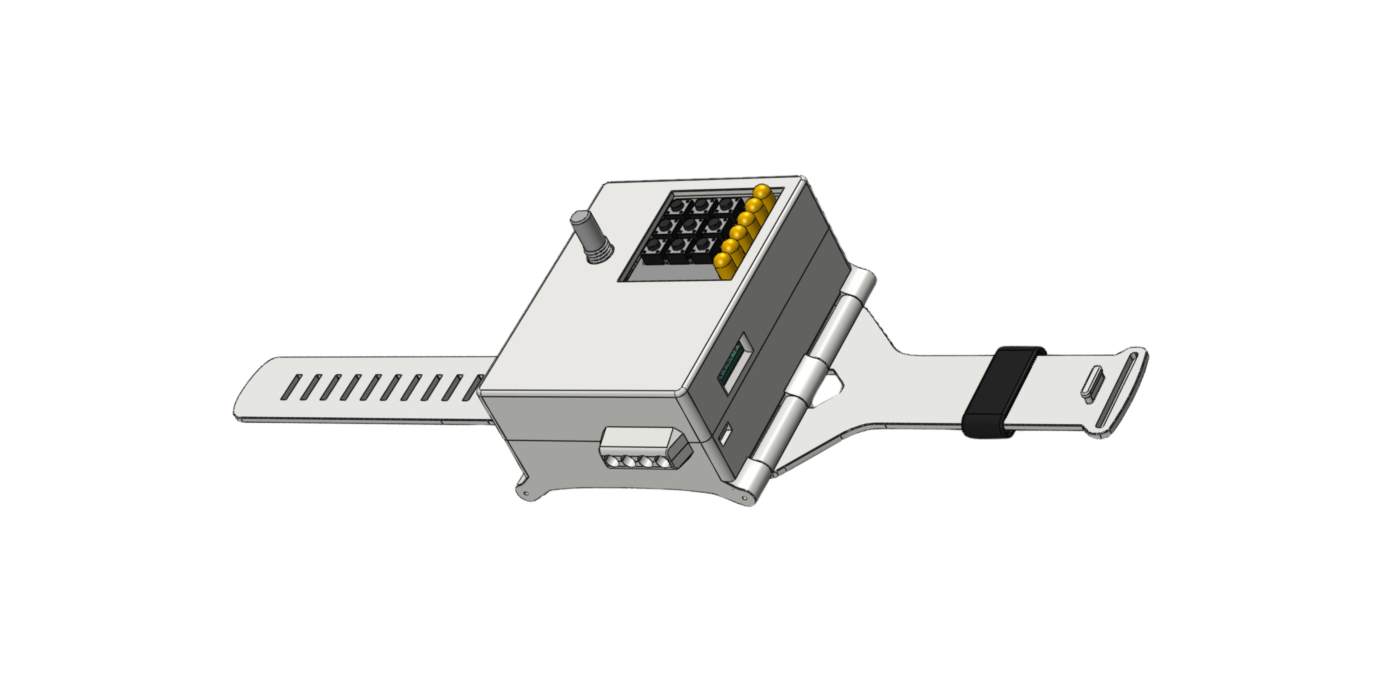
This was still much taller than I had planned on for the dorsally mounted hand enclosure, so I needed to learn CAD software to build the prototype into a wrist-strap form factor instead. My hope is that I can reintroduce the glove idea with, you guessed it, the custom PCB design🙂
CAD Enclosure Design V1
It took a week to learn enough CAD basics to sketch what I wanted well, but once I did, I found it much easier to move elements around and experiment with various design choices. I’d like to get better with the spline tools in mechanical CAD programs in order to model the wires and sensor cables to accompany the rigid components.
Exporting the final STL (Standard Triangle Language) files, I sent them over to my local library to have them printed. Isn’t that amazing that some libraries offer this?


Software 3
Recording / Sequencing
Waiting on the prints gives me time to program the additional MIDI looper feature, and, wow! So this upcoming section opened my eyes to a good deal in terms of the shear diversity of logic “games” you can play with 1’s and 0’s to reach a desired result. Phew. So let’s talk about this code.
To handle our finger-tapped input in a sequenced “loopable” manner, the first order of business is creating an integer array we’ll call “int Mdbchannel []…”. This way we can use “for” loops to iterate through our variable buckets, to capture those delta-times, status bytes, and data bytes discussed earlier. This array was also key in getting the previous MIDI and audio handoff functions working within the sequencer code.
I’ve also modified the way the microcontroller processes the FSR sensor readings using dxinteractive’s “ResponsiveAnalogRead” library. After some trial and error with this, the response times from our sensor input to audio output are feeling much closer to that of a physical instrument. The way I chose to integrate their library was through the use of pointers, where when you have a pointer variable pointing to a memory address, you’re able to retrieve the value stored at that address. Say for example if “ptr” is a pointer variable pointing to an integer, then by using the dereferencing operator (*) in front of the original pointer variable (i.e. “*ptr”), we can access the value of the integer stored at this memory address pointed to by “ptr”.
There’s substantially more than that taking place here, especially in regards to consistently placing ticks on a time grid as patterns begin to get crowded, and a bunch of other features I’m still experimenting with. These are mostly time-keeping related, as well as a file naming feature I’m working on using an RTC (real-time clock). If you have any questions about the code I’ll answer as best I can, or if you notice any programming atrocities I’ve committed, please hit me up! Chances are you’re right, and I’d love to improve:)
Here I was doing a quick test to make sure the recording/loopback function was doing its job:
This code is starting to get a bit long for article format, so until I refactor and organize these blocks into sensible modules, I’ll just be linking ever-lengthier .ino files😬.
ANOTHER NOTE: Although it’s subtle, I’m still seeing a small amount of “Drift” in the recorded SMF files, meaning the distance between notes has some variance while playback is looping. My best guess is the calculations used to loop the audio samples are temporally inconsistent from one trigger to the next, and by extension this affects the exact time our programs gets to the writing of MIDI events. This is a major priority to be addressed in a future update.
Enclosure Assembly (v1)
The prints from my local library are in, so we can get started on assembling this thing! We owe these saints some drum licks, because for 35 grams of TPU and 60 grams of PETG material, the total cost came out to $4.75 ($0.05 USD/gram)!

Before soldering the Teensy to the protoboard, I made sure to solder the two PSRAM (Pseudostatic Random Access Memory) chips I ordered from PJRC’s website. Forgetting this step would be a miniature nightmare trying to desolder each pin later on. The solder blobs on some of these pins also need to be cleaned up a bit.

Ensuring the Teensy 4.1 fit in this enclosure involved removing the micro-USB port. I brilliantly ripped a copper pad off with the microcontroller in doing this, so I had to fish around with some thin wire and a multimeter until I found the conductive copper trace underneath where the pad had been. I applied solder and a few coats of 2-part epoxy in order to keep this lean-to remedy as sturdy as possible while building around it. Here’s a few pictures and a despondent video illustrating the dilemma:


One other hasty modification I made was sawing off the top of the JST adaptor attached to the Adafruit STEMMA speaker with a multitool to make it fit within our design. I made this decision while still designing the first 3D print, and since I’m accessing the speaker via the pads on its board, this didn’t present an issue.
By comparison, the rest of the process was smooth sailing. I cut a piece of protoboard to match its digital placeholder, then soldered the microcontroller, audio shield, and other passive components to it.


I hesitated for a moment before sealing the enclosure due to the impromptu repair of the Teensy’s microUSB D- line, but hey. This is both a prototype and a learning experience, and we won’t have to worry about this issue once we finally get to the PCB design — I probably sound like a broken record at this point!


Enclosure Update (v2)
There were a few modifications I put in for a second iteration on the CAD design, namely 1) Doubling the height of the loop on the wrist strap, and 2) Extruding supports for strain relief, specifically where the FSR wires attach to the protoboard. My plan is to switch to four 3.5mm auxiliary cables to satisfy my detachable sensor requirement in the next update. I also have a hunch this makes sense from a UX point of view, since headphone aux cords/jacks are widely used. For the time being though, these sensors are permanently fastened to the internal protoboard.
Once I assembled the updated version, I fired it up and was pleasantly surprised by how it felt on the wrist. While this needs to be much, much smaller, I’m encouraged enough by the results to move forward with a “Part 2” of this project where we’ll make some software improvements, fine-tune the FSR finger-sleeves, and of course… design the PCB!
To conclude this post, here’s another look at the demo video for “Part 1”, a photo, and a KiCad schematic I’ve drafted for use in the pending update:
Part 1 Final Demo

Circuit Schematic
* Just popping in to say the following schematic diagram is deprecated, and if a newer version hasn’t been posted in Part 2 of this project yet, it will be soon, so stay tuned! *